A pressure–volume diagram (or PV diagram, or volume–pressure loop)[1] is used to describe corresponding changes in volume and pressure in a system. They are commonly used in thermodynamics, cardiovascular physiology, and respiratory physiology.
PV diagrams, originally called indicator diagrams, were developed in the 18th century as tools for understanding the efficiency of steam engines.
A PV diagram plots the change in pressure P with respect to volume V for some process or processes. Typically in thermodynamics, the set of processes forms a cycle, so that upon completion of the cycle there has been no net change in state of the system; i.e. the device returns to the starting pressure and volume.[citation needed]
The figure shows the features of an idealized PV diagram. It shows a series of numbered states (1 through 4). The path between each state consists of some process (A through D) which alters the pressure or volume of the system (or both).

A key feature of the diagram is that the amount of energy expended or received by the system as work can be measured because the net work is represented by the area enclosed by the four lines. In the figure, the processes 1-2-3 produce a work output, but processes from 3-4-1 require a smaller energy input to return to the starting position / state; so the net work is the difference between the two. This figure is highly idealized, in so far as all the lines are straight and the corners are right angles. A diagram showing the changes in pressure and volume in a real device will show a more complex shape enclosing the work cycle. [citation needed] (§ Applications).

The PV diagram, then called an indicator diagram, was developed in 1796 by James Watt and his employee John Southern.[2] Volume was traced by a plate moving with the piston, while pressure was traced by a pressure gauge whose indicator moved at right angles to the piston. A pencil was used to draw the diagram.[citation needed] Watt used the diagram to make radical improvements to steam engine performance.

[3] Specifically, the diagram records the pressure of steam versus the volume of steam in a cylinder, throughout a piston's cycle of motion in a steam engine. The diagram enables calculation of the work performed and thus can provide a measure of the power produced by the engine.[4]
To exactly calculate the work done by the system it is necessary to calculate the integral of the pressure with respect to volume. One can often quickly calculate this using the PV diagram as it is simply the area enclosed by the cycle.[citation needed]
Note that in some cases specific volume will be plotted on the x-axis instead of volume, in which case the area under the curve represents work per unit mass of the working fluid (i.e. J/kg).[citation needed]
In cardiovascular physiology, the diagram is often applied to the left ventricle, and it can be mapped to specific events of the cardiac cycle. PV loop studies are widely used in basic research and preclinical testing, to characterize the intact heart's performance under various situations (effect of drugs, disease, characterization of mouse strains)[citation needed]
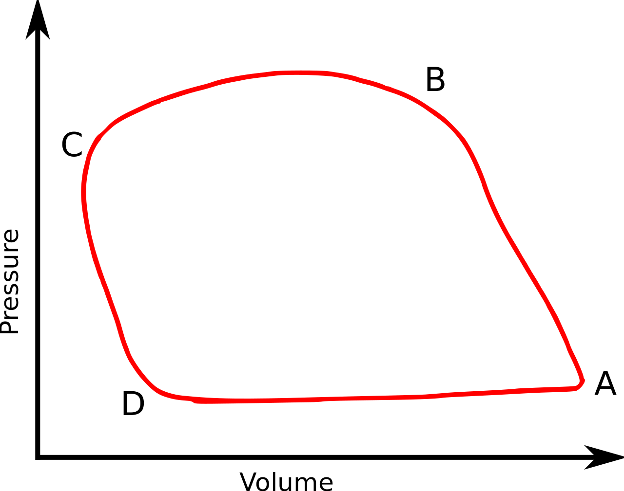
The sequence of events occurring in every heart cycle is as follows. The left figure shows a PV loop from a real experiment; letters refer to points.
.svg/1280px-Diagram_of_the_human_heart_(cropped).svg.png)
As it can be seen, the PV loop forms a roughly rectangular shape and each loop is formed in an anti-clockwise direction.
Very useful information can be derived by examination and analysis of individual loops or series of loops, for example:
See external links for a much more precise representation.