Механизм общей стыковки ( CBM ) соединяет обитаемые элементы в американском орбитальном сегменте (USOS) Международной космической станции (МКС). CBM имеет две отдельные стороны, которые после соединения образуют цилиндрический вестибюль между модулями. Длина вестибюля составляет около 16 дюймов (0,4 м), а ширина — 6 футов (1,8 м). По крайней мере один конец вестибюля часто ограничен в диаметре меньшим проходом через переборку.
Элементы маневрируют в положение готовности к швартовке с помощью системы дистанционного манипулятора (RMS). Защелки и болты на активной стороне CBM (ACBM) тянут фитинги и плавающие гайки на пассивной стороне CBM (PCBM) для выравнивания и соединения двух.
После того, как тамбур герметизирован, члены экипажа расчищают проход между модулями, удаляя некоторые компоненты CBM. Соединители утилит устанавливаются между противостоящими переборками, а закрывающая панель закрывает их. Получившийся туннель может использоваться как погрузочный отсек , пропуская большие грузы с посещаемых грузовых космических кораблей, которые не пройдут через типичный проход для персонала.
Обзор дизайна
Все типы CBM оснащены алюминиевым кольцом, которое прикручивается к корпусу под давлением во время изготовления родительского модуля. Болтовое соединение сжимает два концентрических уплотнительных кольца: одно из силикона (для лучшей температурной производительности), а другое из фторуглерода (для лучшей устойчивости к истиранию). [2] Сопряженная пара колец является основной конструкцией для критически важных для жизни нагрузок давления, поэтому кольца и уплотнения были спроектированы по тем же стандартам, что и оболочки модуля. [3] Если первичные уплотнения изнашиваются, их можно дополнить вторичными уплотнениями, которые были спроектированы и квалифицированы как часть CBM. Вторичные уплотнения могут быть установлены как внутрикорабельная деятельность (IVA). [4]
Большая часть объема вестибюля зарезервирована для прохода экипажа, а закрытие обычно устанавливается по периметру люка в качестве границы прохода. В большинстве мест объем зарезервирован для инженерных соединений за пределами закрытия. Набор инженерных коммуникаций специфичен для каждой пары сопряженных модулей. [5]
Основные типы угольных пластов
Исполнители с номерами деталей квалификации [6]
Помимо своих конструктивных характеристик, ACBM выполняет и реверсирует основные функции, связанные со швартовкой: [7]
Выравнивание физически ограничивает движение между модулями в пяти из шести степеней свободы по мере изменения расстояния между ними. [8] Ограничения накладываются последовательными наборами структурных компонентов. [9]
Индикация готовности к работе защелок захвата предоставляется оператору RMS, когда входящий модуль был правильно размещен в пределах досягаемости защелок. Индикация готовности к защелке обеспечивается четырьмя механизмами: по одному в каждом квадранте, связанному с каждой защелкой.
Входящий модуль захватывается четырьмя защелками. Они тянут его через комбинированное вращение и перемещение, чтобы выровнять PCBM с ACBM с небольшим остаточным зазором. [10]
Устанавливается жесткое структурное соединение. Каждый из 16 приводных болтов на ACBM пересекает остаточный зазор, чтобы ввинтиться в гайку на PCBM. Болты затягиваются в многоэтапном процессе, который постепенно согласовывает два фланца, сжимает уплотнения CBM/CBM и предварительно нагружает соединение CBM/CBM.
Для ACBM были определены два функциональных типа. [11] ACBM типа I с дополнением из 24 независимых механизмов может быть найден как аксиально, так и радиально ориентированным на родительском модуле. Он может быть обращен к любой из шести орбитальных ориентаций, [12] поэтому может находиться где угодно в широком диапазоне температур в начале операций по швартовке. [13]
Тип II ACBM дополняет конструкцию Типа I компонентами для защиты его родительского модуля, когда в порту ничего не пришвартовано. Четыре компонента представляют собой механизмы, которые могут быть развернуты, чтобы убраться с пути входящего модуля. Другие удаляются экипажем после того, как тамбур герметизируется. Тип II используется там, где порты в противном случае были бы открыты в течение длительных периодов времени, или в направлениях, которые испытывают агрессивные условия перед причаливанием. [14] Тип II ACBM находится на радиальных портах узлов ресурсов и может быть обращен в любую орбитальную ориентацию.
Ракеты PMA 1 и PMA 2 были запущены на осевых БРСД узла 1.
PCBM включает в себя фитинги и выравнивающие структуры, соответствующие тем, что установлены на ACBM типа I. 32 фитинга сами по себе являются подпружиненными механизмами, приводимыми в действие во время захвата и придания жесткости соответствующими компонентами ACBM. [15] Первичное уплотнение CBM/CBM также является частью PCBM, как и предварительно нагруженные пружины распорки/выталкивания для стабилизации его относительного движения, когда соединение CBM/CBM почти состыковано. [16]
Для PCBM были указаны два типа, отличающиеся только прочностью уплотнения. Кремниевый материал S383 уплотнения PCBM типа I более терпим к разнице температур до швартовки между двумя модулями, чем фторуглерод V835 типа II. S383 также более устойчив к атомарному кислороду, встречающемуся на орбите перед швартовкой. [17] Тип II использовался для запуска небольших элементов в грузовом отсеке шаттла, будучи прикрепленным болтами к ACBM или к аналогичному оборудованию поддержки полета, поскольку материал V835 более устойчив к разрушающему воздействию трения под воздействием вибрации. [18]
PCBM всегда располагается на конце родительского модуля. Он может быть прикреплен к переборке или в качестве концевого кольца на секции ствола первичной конструкции, которая открыта для вакуума перед причаливанием. [19] PCBM крепятся к модулям, имеющим широкий диапазон тепловой массы, поэтому также могут испытывать широкий диапазон начальных температурных условий. По характеру работы PCBM всегда обращен в ориентацию полета, противоположную ориентации ACBM, поэтому перепады температур могут быть значительными. [20]
Операции
См. Галерею операций для получения дополнительной графики. См. Таблицу миссий для получения информации об отдельных швартовочных событиях.
После запуска
STS-130 MS Роберт Бенкен делает перерыв во время подготовки к выходу в открытый космос баллистической ракеты Nadir ACBM Node 3. [6]
ACBM требуют подготовки к первому использованию на орбите для выхода в открытый космос. ACBM типа I, обычно размещаемые на осевых портах, обычно имеют крышку типа «шапочка для душа», на снятие и укладку которой двум членам экипажа EVA требуется около 45 минут. ACBM типа II, размещаемые на радиальных портах узлов, требуют освобождения пусковых ограничений для развертываемых крышек M/D. Освобождение подпружиненных крышек требует приведения в действие защелок захвата, чтобы закрыть их снова после этого, и, следовательно, проверяет индикаторы готовности к защелке. Включая осмотр, на каждый радиальный порт выделяется около 15 минут для одного члена экипажа EVA, которому при необходимости помогает экипаж IVA для управления ACBM. [21] [22]
Полноразмерные элементы, запущенные на NSTS, имели защитные крышки поверх уплотнения PCBM. Каждому из двух членов экипажа EVA требовалось 40–50 минут, чтобы снять и убрать крышки PCBM, осматривая уплотнение по мере выполнения операции и очищая его при необходимости. [23] PCBM типа II, используемые в качестве интерфейса запуска, осматривались после откручивания болтов, поскольку крышки не устанавливались. Для логистических полетов осмотр осуществляется только камерой. [24] [22]
Причаливание
Подготовка
Проверка действующего общего механизма причаливания во время 56-й экспедиции (примерно в 10 раз больше фактической скорости). [6]
PCBM не требует подготовки к швартовке, кроме той, которая требуется после запуска. Подготовка ACBM к швартовке занимает около часа, начиная с выбора вспомогательных утилит (питание, данные) и последовательной активации для каждой сборки панели контроллера (CPA). Два CPA выбираются в качестве первичного и вторичного главных контроллеров.
Активация запускает встроенный тест и инициализирует счетчики положения для приводов. Каждый привод болта выдвигается на два оборота, затем втягивается на три, чтобы проверить работоспособность как болта, так и двигателя. Защелки приводятся в действие по одной в открытое положение, которое для радиальных портов узла разворачивает крышки M/D. Все 20 приводов устанавливаются в исходные рабочие положения (0 оборотов для болтов, 202° для защелок). Проводится удаленная проверка, чтобы убедиться, что защелки полностью развернуты, а сопряженный коридор и поверхность свободны от препятствий. [25]
Непредвиденные обстоятельства, рассматриваемые во время подготовки, включают очистку поверхности кольца ACBM и корректирующие действия EVA, включающие крышки M/D, а также CPA, Capture Latch и индикаторы готовности к защелке. Существуют специальные процедуры разрешения проблем, связанных с потерей питания и коммуникационной поддержки CBM. [26]
Маневр
Модуль, оснащенный PCBM, маневрирует в зоне захвата с помощью телероботизированной системы дистанционного манипулятора (RMS). Для причаливания модулей использовались две различные RMS: 6-сочлененная система Shuttle RMS (SRMS или « Canadarm ») и 7-сочлененная система Space Station RMS (SSRMS, « Canadarm 2 »).
Операция маневра начинается с захвата полезной нагрузки конечным эффектором RMS. Этот шаг по-разному называют «захватом» или «схватыванием». В эпоху NSTS полезные грузы обычно прибывали в грузовой отсек шаттла. Во время захвата сочленения SRMS «хромали», что позволяло ему приспосабливать свою позу к точному местоположению полезной нагрузки. SSRMS обычно захватывает свободно летящую полезную нагрузку, которая маневрирует, чтобы поддерживать постоянное расстояние и ориентацию по отношению к МКС. После захвата RMS перемещает модуль, изменяя углы его сочленений. Движение модуля часто должно быть организовано с другими движущимися частями МКС, такими как солнечные батареи.
Анимация NASA трех операций стыковки с шаттлом RMS на STS-98. [6]
Визуальная обратная связь о движении PCBM была предоставлена оператору RMS по крайней мере двумя специализированными системами. Ранние причалы управлялись с использованием фотограмметрической техники обратной связи, называемой Space Vision System (SVS), которая была быстро определена как непригодная для общего использования. SVS была заменена специализированной системой Centerline Berthing Camera System (CBCS), впервые использованной на STS-98. [27]
Время, необходимое для выполнения маневра RMS, полностью зависит от траектории, которой необходимо следовать, и от любых эксплуатационных ограничений, которые необходимо учесть. То же самое относится ко всем планам действий в чрезвычайных ситуациях. Ближе к концу маневра оператор преодолевает узкий коридор, когда PCBM начинает сцепляться с ACBM. Операция заканчивается, когда оператор RMS либо видит четыре индикатора готовности к зацеплению на целевой ACBM, либо приходит к выводу, что можно достичь только трех. Поскольку RTL представляет собой подпружиненный механизм, RMS оказывается с запасенной энергией и остается в состоянии, которое может противостоять разделяющей силе. [28]
Приятель
Две половины CBM номинально соединены в три операции:
Capture захватывает и выравнивает входящий PCBM относительно геометрии ACBM.
Nut Acquisition вкручивает каждый болт с приводом в соответствующую гайку
Болт-ап полностью предварительно нагружает соединение между двумя половинами.
По крайней мере два различных протокола захвата были выполнены на орбите. Оба протокола выдают команду захвата «первой ступени» на указанный угол вала между 185° и 187°. Захват первой ступени гарантирует, что каждая защелка расположена над соответствующим фитингом, что оперативно проверяется путем оценки состояния ее переключателя. RMS по-прежнему контролирует положение и ориентацию элемента, а нагрузки, оказываемые защелками захвата, остаются низкими. Захват первой ступени, длящийся около 15 секунд, ограничен орбитальными областями, где наземные контроллеры могут отслеживать ход выполнения в режиме, близком к реальному времени. Для управления ложными нагрузками, когда причальный элемент большой, система управления ориентацией станции может поддерживаться в свободном дрейфе, а упражнения экипажа запрещены. [29]
Два протокола различаются тем, как защелки притягивают две половины в зону досягаемости приводных болтов. В эпоху NSTS была выдана одна команда «захвата» второго этапа после того, как SRMS был переведен в «тестовый режим». Пять этапов захвата выполняются при использовании SSRMS, чтобы ограничить потенциальную нагрузку, накапливающуюся в его стрелах, если происходят нештатные события торможения. В любом случае захват приводит защелки в движение до указанного угла вала 12° за время срабатывания около 108 секунд. В обоих протоколах остаточная энергия в RTL может привести к их кратковременному открытию, поскольку защелки не «зацеплены» за свои крепления, пока не окажутся значительно ниже исходного положения 187°. [30]
Операции RMS и CBM выделены желтым и синим цветом соответственно на этой временной шкале швартовки из STS-120/FD04 Execute Pkg. (NASA/MCC, 2007). Ограничения выделены красным. Команды Powered Bolt были выданы наземными контроллерами после захвата второй ступени. [6]
После того, как оператор приходит к выводу, что процесс захвата успешно завершен, все 16 приводных болтов приводятся в действие со скоростью 5 об/мин с пределом предварительной нагрузки 1500 фунтов силы (6700 Н). Когда тепловые стойки начинают контактировать со своими соответствующими ударными пластинами, результирующая нагрузка сообщается датчиком нагрузки каждого болта. Эта фаза «ABOLT» завершается индивидуально для каждого болта на основе крутящего момента, оборотов или указанной нагрузки. Болты, заканчивающие раньше, могут видеть изменение своей указанной нагрузки, поскольку последующие болты устанавливают свои гайки. Операторы, которые могут находиться на земле, оценивают полученное состояние, чтобы определить, приемлемо ли состояние нагрузки. Если это так, снимаются ограничения на управление положением и выполнение упражнений. RMS освобождает (отцепляет) полезный груз и может приступить к другим задачам. [31] [32]
Если предварительный тепловой анализ показывает, что разница температур между двумя половинами CBM чрезмерна, условие ABOLT удерживается в течение длительного периода времени. «Термическое удержание» позволяет двум сторонам приблизиться к общей температуре. Затем приводные болты затягиваются в шесть этапов до их полной предварительной нагрузки. Каждая команда выдается четырем болтам за раз, с интервалом в 90°. Некоторые этапы могут, по усмотрению оператора, выполняться более одного раза. Окончательная активация болта запланирована на 60 минут, но может значительно варьироваться в зависимости от того, сколько итераций инкрементной предварительной нагрузки выполняется. [33]
Как только оператор определяет, что процесс завинчивания успешно завершен, защелки переводятся в положение «закрыто», а CPA деактивируются. Ресурсы питания, исполнительной команды и данных доступны для переназначения на другие задачи.
В конструкцию CBM заложены приспособления для нескольких нештатных ситуаций. Любой отказ одного болта во время операции стыковки может быть компенсирован уплотнением CBM/CBM, по-прежнему позволяя вестибюлю удерживать атмосферное давление. Любые два отказа болта могут выдерживать механические нагрузки, при условии, что они не находятся рядом друг с другом, а вестибюль не находится под давлением. Потеря любой одной защелки и любого одного индикатора готовности к защелке может быть допущена без риска для успеха миссии, а сами защелки спроектированы так, чтобы компенсировать возможность режимов отказа «тормозов на» в SRMS. Доступна подробная логика разрешения для потери питания и связи, как и последовательности разрешения для защелок, которые «пропускают» свои фитинги или заклинивают при частичном ходе. Процедуры непредвиденных обстоятельств на этом этапе операций также решают проблему ненормального торможения SSRMS и «быстрого обеспечения безопасности», если другие системы в МКС или шаттле требуют немедленного вылета. [34]
Операции IVA
Пилот STS-92 Памела Мелрой определяет два блока панели управления (CPA), которые необходимо убрать из вестибюля Зенита Узла 1. [6]
Оснащение вестибюля включает в себя установку оборудования, проверку на герметичность и механическую перенастройку. Требуемое время и усилия зависят от конфигурации ACBM, количества и типа компонентов CBM, которые необходимо удалить, и интерфейсов, которые необходимо соединить между двумя элементами. Бюджет может составлять до десяти часов, хотя, по крайней мере, в некоторых случаях это время может быть приостановлено для проведения расширенной «точной проверки на герметичность» путем снижения давления перед открытием люка в вестибюль.
Поскольку они перекрывают коридор для экипажа через вестибюль, CPA всегда должны быть убраны, [35] и всегда необходимо снимать любые крышки через люк на недавно пришвартованном элементе. Там, где элементы будут оставаться сопряженными в течение длительного времени, другие компоненты CBM могут быть удалены для безопасного хранения или повторного использования. Радиальные порты узла требуют дополнительных 20–40 минут для снятия и хранения центральной секции крышки M/D. Панель закрытия обычно устанавливается по внутреннему периметру двух противостоящих друг другу люковых балок, чтобы смягчить постепенное скопление мусора по периметру вестибюля. [36]
Подробные аварийные операции, охватывающие как ремонт, так и профилактическое обслуживание, были подготовлены заранее для внутренних компонентов. Обобщенные процедуры для точного определения утечки воздуха в вестибюле существуют по крайней мере с этапа сборки МКС 4A, как и аварийные процедуры установки для всех трех наборов уплотнений IVA. Сообщения о повреждении разъемов CPA (как на земле, так и на орбите) привели к развертыванию процедур снижения риска на STS-126 . [37]
Дебертинг
Удаление элемента по сути меняет процесс швартовки на противоположный. [38] Это зависит от особенностей конфигурации тамбура для операций. Наиболее часто встречающаяся реализация начинается с демонтажа тамбура при переконфигурации для дешвартовки логистического элемента из радиального порта узла. Первоначально бюджет процедуры был рассчитан на двух членов экипажа и продолжительность 4 часа. Она удаляет элементы, которые пересекают план интерфейса ACBM/PCBM (закрытие, перемычки и заземляющие ремни), устанавливает оборудование CBM, необходимое для операций по дешвартовке (например, CPA, тепловые чехлы), и закрывает люк. [39]
Оборудование для испытания на падение давления, включая датчики и вспомогательную электронику, а также вакуумный соединительный джампер длиной 35 футов (11 м), впоследствии устанавливаются на внутренней стороне люка. После установки всего этого тамбур готов к периоду сброса давления около 40 минут, включая периоды выдержки для проверки на герметичность. Критическое (абсолютное) давление составляет 2 мм рт. ст. (267 Па) для того, чтобы исключить повреждение уплотнений CBM во время сброса давления. [40]
Как и при подготовке к причалу, вспомогательные утилиты настраиваются для подачи питания и данных в CBM. Питание подается, два CPA выбираются для использования в качестве основного и дополнительного главных контроллеров, и инициализируются отдельные контроллеры двигателей. Команда "DBBoltck" выдается на приводные болты, а захватные защелки индивидуально управляются на угол вала 212°. Затем защелки устанавливаются в номинальное положение "завершения захвата" 12°. CBM либо остается в состоянии "ожидания", либо отключается. [41]
После дебаркадера закрытие крышек надирного CBM Harmony.
Освобождение элемента PCBM из жесткого сопряженного состояния занимает около 90 минут. Оно начинается с ослабления всех 16 силовых болтов примерно на 0,4 оборота, что занимает менее пяти минут. [42] Все 16 болтов должны иметь положительную остаточную нагрузку после завершения шага. [43] Затем полностью извлекаются наборы из четырех болтов, каждый набор занимает около 6:30, чтобы достичь номинального положения в 21,6 оборота. Захват RMS и управление ориентацией свободного дрейфа должны быть на месте до извлечения третьего набора. После того, как все 16 болтов будут извлечены, защелки захвата раскрываются, позволяя сжатым индикаторам готовности к защелке упираться в направляющие выравнивания PCBM. Отходящий элемент маневрируется RMS, и на радиальных портах узла закрываются развертываемые крышки M/D. Затем ACBM отключается путем отключения питания от CPA. [44]
Разрешение непредвиденных обстоятельств во время демате обычно похоже на разрешение для подготовки и выполнения операций по стыковке. Многие из них фактически заканчиваются инструкциями по непредвиденной перешвартовке, чтобы позволить извлечение и замену компонентов CBM. Усилия по переоборудованию вестибюля для дешвартовки CBM делают его в целом непригодным для аварийного отплытия. [45]
Возможности
Первоначальный проект МКС предусматривал установку элемента Habitat на порту, обращенном к надиру, узла 1 (Unity), и проходы через переборки были спроектированы соответствующим образом. По мере того, как станция проходила первые этапы сборки, узел 3 был запланирован для этого места. Позже стало очевидно, что установка на переборке с левой стороны даст значительные эксплуатационные преимущества. К сожалению, первоначальная прокладка коммуникаций внутри узла 1 потребовала значительной переделки на орбите, чтобы обеспечить возможность изменения. Большой диаметр CBM позволил использовать PMA3 в качестве замыкания, удерживающего давление, во время работ, так что проходные отверстия можно было снимать и заменять без выхода в открытый космос. Во время Экспедиции 21 PMA3 был перемещен в CBM с левой стороны, и «...кабели питьевой воды, ISL и данных 1553, а также установка воздуховодов, кабелей и шлангов IMV [межмодульной вентиляции]...» были подключены в рамках подготовки к прибытию Узла 3. Реконфигурированная переборка была проверена на герметичность перед перемещением PMA3 обратно в место хранения, а Узел 3 был установлен в новом подготовленном месте на STS-130 . [46]
Бортинженер 61-й экспедиции Джессика Меир позирует перед малогабаритной спутниковой установкой SlingShot, загруженной восемью спутниками CubeSat .
Глубина, диаметр и доступность CBM также использовались для поддержки распределения CubeSats из системы развертывания SlingShot. Каркас монтируется во внутреннюю оболочку PCBM на логистических транспортных средствах (например, Cygnus ). Модуль шлюза Bishop NanoRacks (NRAL) использует преимущества надежного интерфейса между ACBM и PCBM для многократной пристыковки и отстыковки «колокола», размещающего аналогичные возможности. [47]
История развития
Основные факторы, влияющие на CBM, были продемонстрированы во время облета STS -135 после расстыковки . Путь PCBM во время захвата индуцируется RMS (1). RMS взаимодействует с модулями, вес которых варьируется от Cupola (2) и PMA (3) до Kibō (4). Масса взаимодействует с освещением, вызывая разницу температур между кольцами CBM. Это добавляет отклонения, вызванные давлением, особенно для радиальных портов (5). [48]
Концепция причаливания в космической программе США была разработана для смягчения проблем орбитальной механики, которые возникали в ходе эволюции стыковки. Хотя CBM и не был первым механизмом, разработанным специально для причаливания, он был первым подобным устройством, разработанным в США специально для сборки структурных соединений, которые выдерживали бы давление на уровне моря. Он объединяет четыре архетипических особенности:
Напорные конструкции испытывают внутреннее давление в дополнение к другим основным нагрузкам. [49] Они считаются критически важными для жизни, когда используются в качестве прочного корпуса отсека с экипажем. В этом контексте им уделяется особое внимание в таких вопросах, как нагрузки, скорость утечки, избыточность уплотнений и методы проверки. Они также привлекают пристальное внимание к последствиям их отказа. [50]
Внешние фланцы подвергаются как механическим нагрузкам, так и нагрузкам, вызванным давлением в их исходных сосудах под давлением. Относительная жесткость фланца определяет, как свободный конец изменит форму. Деформации должны быть учтены, когда что-то крепится к фланцу. [49]
Движущиеся механические узлы передают силы по-разному при изменении их положения. На их нагрузки влияет внутреннее трение, и они часто требуют большего количества итераций анализа и проектирования, чем конструкции. В случае CBM путь нагрузки включает как модуль, так и RMS, поэтому может быть очень сложным. [51]
Структурные соединения, устойчивые к высокому вакууму, спроектированы так, чтобы строго ограничивать зазоры в соединении, а условия, в которых они собираются, тщательно контролируются. Для CBM эти проблемы усугубляются во время болтового соединения очисткой уплотнения, поскольку предварительные прогибы согласуются, а также любой пылью и мусором, попавшими в соединение. [52]
Использование этих функций на космическом корабле влечет за собой особые соображения из-за агрессивной среды. На типичной высоте МКС в 255 морских миль (472 км) НАСА выделяет семь факторов для этой среды: [53]
Интенсивность потока метеороидов, попадающих в CBM, сильно варьируется в зависимости от ориентации установки. [6]
Состав, свойства и состояние окружающей нейтральной атмосферы. В частности, атомарный кислород (AO) является высококоррозионным для многих материалов. Эластомеры, такие как лицевое уплотнение PCBM, особенно чувствительны к AO. Низкое давление и низкая абсолютная влажность также влияют на коэффициент трения для многих комбинаций материалов. Воздействие очень низких давлений также изменяет химический состав некоторых материалов с течением времени. [54]
Сильно направленные источники и приемники лучистой энергии . Монтаж, оптические свойства и изоляция открытых компонентов космического корабля спроектированы для поддержания приемлемых температур. В некоторых случаях орбитальная ориентация всего космического корабля динамически контролируется для смягчения этих эффектов. [55] [56]
Геомагнитное поле может мешать работе чувствительных электрических компонентов (таких как датчики, переключатели и контроллеры ACBM). Последствия могут включать в себя полный отказ, поскольку компоненты проносятся через поле. [57]
Ионизированные газы , которые загрязняют и заряжают открытые поверхности, которых в CBM много. Большинство космических аппаратов решают эту проблему путем тщательного заземления открытых компонентов. [58]
Электромагнитное излучение, которое может изменить энергетическое состояние электронов в питаемом оборудовании. Двигатели, датчики и управляющая электроника, такие как на ACBM, подвержены этим эффектам, если они не экранированы. [59]
Метеориты и орбитальный мусор, некоторые из которых могут быть как тяжелыми, так и быстро движущимися, которые могут ударить по космическому кораблю. Хотя конструкция CBM была дополнена несколькими различными способами в этом отношении, проблема была разработана на уровне интегрированного космического корабля; количественные требования не выделены ни в одной спецификации CBM. [56] [60]
Баланс между гравитационным и центробежным ускорениями (часто называемый «нулевой гравитацией»), который имеет существенные последствия для проверки движения механизмов на земле, поскольку там доминирует гравитация. CBM следовал типичной практике проектирования космических аппаратов, чередуя анализ и испытания для разработки и проверки конструкций для этого состояния. [51]
Некоторые из этих особенностей и факторов взаимодействовали в ходе длинной последовательности решений об орбите станции, конфигурации, планах роста, средствах запуска и методах сборки. Операция по причаливанию берет свое начало в программах 1960-х и 1970-х годов, когда они исследовали практичность физики, связанной с этими вопросами. Сама концепция CBM начала появляться с первыми исследованиями программы в начале 1980-х годов, прошла через несколько итераций концепции и завершила разработку незадолго до запуска первого элемента полета, когда 1990-е годы подходили к концу.
Происхождение (до 1984 г.)
CBM — это всего лишь одна ветвь в долгой эволюции способности Соединенных Штатов собирать большие космические корабли. По крайней мере, еще в конце 1950-х годов эта способность была признана «... необходимой для строительства космических станций и сборки аппаратов на низкой околоземной орбите...». К концу программы «Аполлон» стандартизированные методы сближения и стыковки для ее поддержки были доказаны на практике. Основные проблемы управления топливом были хорошо поняты, как и проблемы со стабильностью управления и загрязнения, возникающие из-за струй реактивной системы управления преследующего аппарата [61], поражающих целевой аппарат во время операций сближения. [62]
Операции по стыковке часто требуют сложных маневров, чтобы не потревожить целевой корабль. [6]
Появление программы Space Shuttle смягчило некоторые проблемы со стыковкой, но внесло новые. Значительные различия между массами преследуемых и целевых транспортных средств обеспечивали менее равное распределение импульса после контакта, а большая масса Shuttle требовала значительно больше тормозного топлива, чем требовалось во время Apollo. Простое соосное выравнивание между инерционными свойствами преследования и цели во время операций по сближению на конечном участке было невозможно с асимметричным Orbiter, который был разработан для аэродинамического подъема во время возвращения с орбиты. Удар больших струй RCS Shuttle по относительно небольшим целевым транспортным средствам также нарушал контроль над ориентацией цели во время операций по сближению. Эти проблемы заставили изменить стратегию торможения в программе Shuttle. Не все стратегии были легко реализованы во всех орбитальных направлениях, что угрожало возможности сборки в некоторых из этих направлений. Использование длинного телеробототехнического устройства (RMS) уменьшило эту угрозу, переместив точку первого касания от преследуемого транспортного средства. [63]
К 1972 году анализ требований к программе «Шаттл» показал, что почти 40% задач миссии будут включать сборку путем размещения полезной нагрузки в грузовом отсеке орбитального аппарата. В то время предполагалось, что многие из извлеченных космических аппаратов не будут предназначены для таких операций, что еще больше повысило важность решения (или устранения) проблем со стыковкой. Операция стыковки была разработана для этого: требование аккуратного захвата близлежащего космического аппарата с почти нулевой скоростью контакта было отнесено к запланированной RMS «Шаттла». Использование RMS для сборки объектов на орбите рассматривалось как движущее требование к точности как положения, так и ориентации формирующейся системы. [64]
Хотя это и не было предусмотрено во время разработки RMS, в этот период появились требования, которые стали важными для CBM: точность и правильность управления RMS, ограничения его способности приводить все в соответствие и величина структурных нагрузок, достигающих пика в стрелах и соединениях во время захвата. Они оказались решающими для проектирования, квалификации и эксплуатации механизма разработки. [65]
Целевая группа по космической станции определила стыковку как основной метод сборки. [6]
SRMS не выполнял свой первый поиск и причаливание в грузовом отсеке до STS-7 в июне 1983 года. Дата первой операции была назначена на два месяца после подачи окончательных отчетов восемью подрядчиками NASA по исследованию потребностей, характеристик и архитектурных вариантов космической станции. Несмотря на то, что на момент написания окончательных отчетов по исследованию результаты полетов еще не были доступны, по крайней мере три из них определили «причаливание» как основной способ сборки космической станции из герметичных модулей, доставленных в грузовом отсеке шаттла. Из описанных и проиллюстрированных концепций ни одна не сильно напоминает окончательный дизайн CBM, и доступно мало обсуждений технических деталей. [66]
В начале 1984 года целевая группа космической станции описала механизм причаливания, который ослаблял бы нагрузки, возникающие при маневрировании двух модулей в контакте друг с другом, с последующим защелкиванием. Условия контакта были определены как важные, но в то время не были количественно определены. То же самое относится и к диаметру внутреннего прохода. Внутреннее соединение коммуникаций между модулями было явно необходимо, как и «андрогинность». Стандартизированный механизм причаливания воспринимался как внешний фланец на портах модуля, а «6-портовый многопортовый адаптер причаливания» примерно соответствовал окончательной концепции узла ресурсов. Прогибы, вызванные внутренним давлением, действующим на радиально ориентированные порты цилиндрических модулей, были признаны критически важной проблемой разработки. [67] Окончательный отчет целевой группы также, по-видимому, является одним из самых ранних упоминаний о «общих... механизмах причаливания». [68]
Продвинутая разработка/Фаза B (ок. 1985 – ок. 1988)
База знаний о причаливании росла в течение 1980-х годов по мере разработки других механизмов причаливания. Они включали такие системы, как защелка Flight Support Structure (см. здесь) и система развертывания и извлечения полезной нагрузки Shuttle. [6] [69]
Параллельно с текущими исследованиями конфигурации на уровне системы, НАСА ожидало, что проекты по разработке концепций для усовершенствованных механизмов стыковки и швартовки «...для существенного снижения стыковочных нагрузок (скорости менее 0,1 фута/сек) и обеспечения возможностей швартовки полезной нагрузки... будут инициированы, начиная с 1984 финансового года». [70]
Программа усовершенствованной разработки механизма причаливания фактически началась в 1985 году, что привело к полномасштабным испытаниям на испытательном стенде с шестью степенями свободы в Центре космических полетов им. Маршалла (MSFC). В этих усилиях «общий», по-видимому, означал, что одно семейство конструкций механизмов выполняло как причаливание, так и стыковку (унаследовав расходящиеся требования для обоих), и что любой член семейства мог присоединиться к любому другому члену. «Активный» и «пассивный» относились к тому, были ли предусмотрены механизмы для ослабления остаточной кинетической энергии после стыковки. Моторизованные защелки захвата двух разных конструкций (быстродействующие и медленнодействующие, имеющие короткий и длинный радиус действия соответственно) были установлены на внешнем радиусе. Направляющие лепестки, ориентированные наружу, также были расположены на внешнем радиусе, что дало механизму общий диаметр около 85 дюймов. [71]
Художественная концепция модулей NASA (январь 1989 г.) [6] [72]
Структурное защелкивание было достигнуто с помощью «структурного защелкивания болта/гайки» номинальным диаметром 0,500 дюйма. Спроектированные для растягивающей нагрузки 10 000 фунтов силы (44 500 Н), как болт, так и гайка были изготовлены из стали A286, покрытой сухой пленочной смазкой дисульфида вольфрама, как указано в DOD-L-85645. Места расположения болта/гайки чередовались по ориентации по периметру стенки давления диаметром 63 дюйма, а поверхности обоих колец включали уплотнения, так что механизм был фактически андрогинным на уровне сборки. Болты были спроектированы для ручного приведения в действие с использованием герметичных проходок привода через переборку. Была определена возможность моторизованного затягивания, но не спроектирована. Болт можно было затягивать как со стороны головки, так и со стороны гайки. Ни крутящий момент, ни неопределенность предварительной нагрузки не указаны в имеющейся документации. [73]
Один из четырех вариантов исследования включал алюминиевые сильфоны, что позволяло замкнуть петлю модулей. Нагрузки растяжения, вызванные внутренним давлением, переносились через сильфоны непрерывной кабельной петлей, продетой через 47 шкивов, расположенных вокруг внешней части сильфонов. Не все проблемы с конструкцией сильфонов, по-видимому, были полностью решены к концу серии испытаний на разработку. [74]
Хотя размеры вмещали внутренние инженерные соединения и 50-дюймовый квадратный люк, оболочка механизма имела ограниченную совместимость с окончательными утопленными расположениями радиальных портов на узлах ресурсов USOS. Очевидная несовместимость с расположениями радиальных портов может быть объяснена пока еще нестабильной конфигурацией узлов, которые в некоторых конфигурациях показаны как сферические модули с 10 портами, но цилиндрические модули с 3 портами в других. Многие другие особенности базовой конфигурации станции того времени также кажутся совершенно отличными от окончательной МКС. [75]
Космическая станция «Фридом» (ок. 1989 – ок. 1992)
Четыре «стойки», которые можно увидеть здесь во время сборки американского лабораторного модуля «Destiny», обеспечивают пространство для распределения служебных (питание, данные и т. д.) коммуникаций по стойкам. Этот архитектурный подход стал истоком большого диаметра CBM.
По мере приближения 1990 года размер CBM стабилизировался за счет особого инженерного подхода к проектированию модулей. Косвенно ограниченный круглым поперечным сечением отсека полезной нагрузки NSTS, внутренний объем модуля был разделен на одиннадцать областей. Центральный проход, проходящий по всей длине модуля, окружен четырьмя блоками оборудования. Блоки оборудования встречаются вдоль четырех линий, проходящих почти по всей длине оболочки давления. Сразу за этими точками клиновидные объемы коммуникаций идут параллельно проходу. Коммунальные трассы позволяют подключаться к ним со многих станций по всей их длине. Другое оборудование, часть которого облегчает подключение коммуникаций между модулями после их стыковки на орбите, более эффективно упаковано в объемах концевого конуса, чем в цилиндрической части модуля. Проходы для этих коммуникаций для соединения между модулями получили значительное внимание в макете вестибюля и, следовательно, CBM. [76]
Каждый блок оборудования был разделен на «стойки» стандартного размера, которые могли быть установлены на орбите для ремонта, модернизации или расширения возможностей станции. Стойки, содержащие соответствующее оборудование, могли быть интегрированы и испытаны на приемку на земле перед запуском. Такой подход к интеграции способствовал более высокому уровню проверки, чем это было бы возможно при замене более мелких компонентов, обеспечивая «...легкую перенастройку модулей в течение их срока службы в 30 лет». Это также позволило архитектуре приспособиться к последующему изменению наклонения орбиты путем перемещения некоторых тяжелых стоек с первоначального запуска модуля. Отличительные размеры и форма как общего люка, так и CBM позволили реализовать эту концепцию интеграции модулей, поскольку они позволяли перемещать большие стойки в модули и из них во время нахождения на орбите. [77]
Три конфигурации CBM для программы космической станции Freedom, современные с подробными иллюстрациями в Illi (1992) и Winch & Gonzalez-Vallejo (1992). [6]
Другие системные решения в этот период времени также повлияли на окончательный дизайн CBM. Идея «общего» механизма для стыковки и швартовки, по-видимому, была отвергнута, и были определены основные механизмы, специфичные для каждой из этих отдельных операций. Концепция «общей» модульной оболочки давления с рядом конфигураций радиальных портов, все еще изучавшаяся NASA по крайней мере до 1991 года, была отвергнута в пользу выделенных «узлов ресурсов», имеющих четыре радиальных порта вблизи одного конца цилиндрической оболочки давления. Закрытие «модульной модели» было отложено от первоначального дизайна системного уровня к 1992 году, что исключило вариант PCBM на основе сильфона. [78]
Концепции причаливания развивались параллельно с разработкой CBM. Здесь показан шестирукий «захват» Intelsat 603 в случае чрезвычайной ситуации во время выхода в открытый космос 3 миссии STS-49 в 1992 году.
К началу 1990-х годов начала вырисовываться более подробная картина CBM. Первоначальный выпуск спецификации разработки PCBM состоялся в октябре 1991 года, за ним последовал выпуск CBM/PE ICD в феврале 1992 года и спецификации разработки ACBM в январе 1993 года. [79] Несколько элементов концепции Advanced Development были сохранены с небольшими изменениями. Структурная защелка болта/гайки и 4-стержневые захватные защелки остались, хотя диаметр болта увеличился до 0,625 дюйма (15,9 мм). Как болты, так и захватные защелки были моторизованы с возможностью ручного резервного копирования, хотя отдельные механизмы по-прежнему приводились в действие посредством герметичных муфт, которые проходили через переборку. Термин «активный» эволюционировал, чтобы означать совместное расположение всех устройств с питанием на стороне интерфейса, уже присутствующего на орбите, когда произошла операция стыковки. [80]
Другие характеристики были изменены более существенно с момента появления концепции Advanced Development. «Андрогинность» была отброшена: все 16 болтов были собраны на одной стороне интерфейса CBM/CBM, а сторона гайки больше не описывалась как управляемая. 8-канальный мультиплексный контроллер двигателя мог дистанционно переключаться между защелками, при этом для каждого модуля с ACBM требовалось два контроллера. Датчики перепада давления были включены для контроля потенциальных мест утечек. До его отмены пассивный гибкий CBM все еще имел алюминиевые сильфоны, но концепция кабеля/шкива была заменена набором из 16 силовых стоек, приводимых в действие мультиплексным контроллером двигателя. Конструкция уплотнения CBM/CBM была «лицевой» конструкцией, только с одной стороны интерфейса. Направляющие выравнивания были развертываемыми, и их ориентация была обращена внутрь. Четыре захватных защелки приобрели фрикционные муфты, что позволяло им приводиться в движение в обратном направлении. [80]
В этот период времени появились новые особенности. В концепцию ACBM была добавлена крышка от мусора. Это был цельный блок полного диаметра, снятый и замененный RMS. Крепление колец к их переборкам было определено как 64-болтовая схема, но ни в одном из источников не упоминается дифференциация схемы болтов. В конструкцию была добавлена стяжка, работающая на сдвиг, для переноса нагрузок параллельно плоскости интерфейса CBM/CBM. [80]
Переход к МКС (1993 – ок. 1996)
Характеристики МКС в том виде, в котором она была запущена, можно увидеть в варианте A-2, разработанном целевой группой по перепроектированию космической станции. [6]
К декабрю 1990 года смета расходов на космическую станцию Freedom выросла с 8 миллиардов долларов, как в 1984 году, до 38 миллиардов долларов. Хотя к марту следующего года смета была снижена до 30 миллиардов долларов, в Конгрессе звучали призывы реструктурировать или отменить программу. В марте 1993 года администратор НАСА Дэн С. Голдин сообщил, что президент Клинтон хотел, чтобы «текущая космическая станция была перепроектирована как часть программы, которая более эффективна и действенна... [чтобы]... значительно сократить расходы на разработку, эксплуатацию и использование, достигнув при этом многих текущих целей...». [81]
Группа по перепроектированию представила свой окончательный отчет в июне 1993 года, описав три различные концепции космической станции. Каждая концепция была оценена при наклонении орбиты 28,5 и 51,6 градуса, чтобы выявить любые проблемы поддержки со стороны американских и российских стартовых комплексов соответственно. Ни одна из трех конфигураций не соответствует в точности конструкции МКС в том виде, в котором она существует сегодня, хотя некоторые из них имели сильное сходство с окончательной конфигурацией. CBM была единственной явно идентифицированной структурной/механической подсистемой, включенной во все варианты при всех наклонениях. Для всех вариантов было рекомендовано повышенное использование объема вестибюля для подключения к коммуникациям с целью сокращения времени выхода в открытый космос. Удаление автоматизированных контроллеров, двигателей и механизмов защелок было концептуально определено как вариант для одного из них. [82]
Конкретные концептуальные проекты, которые появились в результате работы Целевой группы, вскоре были преодолены событиями. К концу 1994 года США, Россия и международные партнеры в принципе согласились объединить свои национальные усилия в единый проект «международной [sic] космической станции». Сотрудничество привело к гибридным сборочным операциям, таким как установка стыковочного модуля на вершине стыковочной системы орбитального корабля на STS-74 . Это размыло общие различия между причаливанием и стыковкой, которые позиционируются RMS, но приводятся в действие срабатыванием двигателей орбитального корабля. [83]
Обе спецификации CBM были полностью переписаны в 1995 (PCBM) и 1996 (ACBM) в рамках переходного процесса. В этот период также произошло разделение ICD на специализированную Часть 1 (требования к интерфейсу) и Часть 2 (физическое и функциональное определение) в Ревизии D (июнь 1996). [79] К тому времени, когда в декабре 1996 года была установлена окончательная структура для международных усилий, первые симуляторы CBM уже были доставлены в NASA. [84]
Квалификация (ок. 1994 – 1998)
Будучи указанными независимо, соответствие большинству требований ACBM и PCBM проверялось отдельно. [85] В дополнение к мероприятиям на уровне сборки для ACBM и PCBM, данные о соответствии были получены для подсборок, таких как Capture Latch, Powered Bolt, Powered Bolt Nut и Ready to Latch Indicator. [86] Например, функциональность Powered Bolt и Nut была квалифицирована с помощью испытаний на уровне компонентов, которые включали функциональные испытания окружающей среды, случайную вибрацию, тепловой вакуум и, для болта, тепловой цикл. [87] Испытания нагрузки в условиях текучести и предельных статических условиях проводились на уровне компонентов, как и в динамических условиях. Критерии успеха для этих испытаний, как правило, основывались на крутящем моменте, необходимом для установления и снятия предварительной нагрузки, на электрической непрерывности и на точности тензодатчика болта. [88]
Напротив, по крайней мере 11 указанных проверочных мероприятий требовали совместной проверки сопряжения и/или разъединения двух сторон. [89] Из них пять требовали анализа, подтвержденного испытанием и/или демонстрацией, которая требовала определенного сочетания обстоятельств и интерфейсов. Например, спецификации предписывали, чтобы захват был квалифицирован «... анализом при динамических нагрузках, накладываемых SRMS и SSRMS... подтвержденным испытанием на уровне сборки, которое включает изменение производительности в результате температуры и давления на ACBM и PCBM и на их взаимодействующих структурах». [90] Анализы Boltup интерфейса ACBM/PCBM и последующей утечки требовали аналогичной проверки испытаниями на уровне элементов и сборки, которые включали искажающие эффекты давления и температуры. Сквозные демонстрации также требовались на уровне сборки для проверки «... механической функциональности... без прерывания выполнения индикации готовности к защелке и захвата». [91]
Хотя редизайн станции 1993 года рекламировал несколько изменений в конструкции CBM, несколько из них были введены к моменту проведения теста на тепловой баланс, включая тепловые стойки и ударные пластины (1), индикаторы готовности к защелке (RTL) (2), крышки для уплотнительных площадок IVA (3), внешние приводы (4), штифты и гнезда выравнивания (5) и специальные контроллеры (6). RTL, направляющие выравнивания (7) и защелки захвата (8) еще не достигли конфигурации полета. [6] [92]
Наложение комбинированных эффектов динамики захвата и искажений потребовало итераций анализа и проверки теста для каждого аспекта. Специальная тестовая установка была разработана в трех параллельных потоках: [48]
Анализ динамики контакта ранних версий CBM начался в 1992 году и был включен в модель MSFC RMS для использования в тестах разработки модели CBM Boeing. Модель была основана на «методе мягких ограничений», оценивая «...пересечение или проникновение между соответствующими поверхностями и вычисляя взаимно перпендикулярные силы, пропорциональные глубине проникновения». Предварительное тестирование проверки модели для этих сил «отскока» и последующих ускорений проводилось в Лаборатории динамики контакта MSFC с 1992 по 1997 год. [93] Нагрузки были локально линеаризованы и приложены к заднему концу испытательного изделия PCBM в совместных тестах и демонстрациях с помощью уравновешенной «системы резистивной нагрузки», подвешенной к верхней части вакуумной камеры V20 MSFC. [94]
Прогнозы температуры основывались на стандартных методах моделирования термического анализа. Модель была проверена с помощью автономного испытания теплового баланса обеих сборок в 12-вольтовой термической вакуумной/солнечной камере моделирования AEDC в 1995/96 годах. Они гарантировали использование правильных проводимостей интерфейса, внутреннего переизлучения и внутренних тепловых емкостей. Проверка была поддержана выбором испытания проводимости контакта, что сократило количество переменных, которые должны быть разрешены в тепловом балансе. [95] Температуры были заданы во время квалификационного испытания на уровне сборки с помощью комбинации ленточных нагревателей, криогенных кожухов и прямой инъекции жидкого азота . [ 96]
Прогибы элементов под давлением, вызванные давлением, оценивались с помощью конечно-элементного моделирования их первичных оболочек давления, что привело к проверке испытаний под давлением в середине 1996 года. Для испытаний на уровне сборки CBM 16-футовый (4,9 м) активный сосуд под давлением (APV) имитировал граничные условия на радиальной причальной плите, похожей на полет. При эмуляции использовались 32 внешних структурных дублера толщиной от 0,125 до 1,00 дюйма (3,2–25,4 мм), 32 внутренние стойки и 16 пневматических приводов для настройки жесткости, ограничения прогибов и приложения локальных радиальных нагрузок соответственно. Более простой 9-футовый (2,7 м) пассивный сосуд под давлением имитировал осевой порт. Изготовление APV совпало с обнаружением отрицательных запасов в конструкции радиальных причальных плит узла 1. Перепроектирование плиты не могло быть включено в производственный график APV. Это компенсировалось относительным вращением команд захвата гайки во время теста. [97]
Сообщаемые диапазоны температур, пригодные для эксплуатации CBM, [13] на которые сильно влияют воздействие солнечного света, Земли и фонового излучения дальнего космоса. [20]
Подготовка к тесту на уровне сборки началась с модификации камеры в августе 1996 года, а два сосуда высокого давления были доставлены для характеристического тестирования в декабре. Комплексная проверка собранной установки в камере V20 началась с базового тестирования оборудования CBM в августе 1997 года и была завершена в ноябре того же года. Формальное тестирование проходило в три этапа с февраля по сентябрь 1998 года:
На этапе A было выполнено 62 цикла затяжки болтов в различных атмосферных и температурных условиях для оценки скорости утечки и срока службы приводных болтов/гаек.
Фаза B включала 35 частичных циклов (захват и сбор орехов) в расширенном диапазоне температурных условий.
На этапе C было проведено пять демонстраций в «сложных» условиях: экстремальные перепады температур в сочетании с более удаленными положениями PCBM, чем те, которые ранее выполнялись в аппаратном обеспечении. [98]
Ни один тест на утечку не был провален в этом тесте. Модель динамики контакта коррелировала с результатами теста с высокой статистической достоверностью и, как было показано, не имела заметной чувствительности к отклонениям. Были выявлены и проверены сигнатуры износа для Powered Bolt, а также были выявлены и решены несколько проблем интеграции посредством незначительной переделки конструкции. Были обнаружены существенные проблемы с разгрузкой гравитационных эффектов, специфичных для теста, что в конечном итоге привело к изменениям в процедурах полета. Были исследованы номинальные и непредвиденные процедуры, а в некоторых случаях они были существенно пересмотрены перед полетами. [99]
Впоследствии на объекте были проведены испытания для квалификации уплотнений IVA и поддержки решения проблем с операциями миссии, касающихся досягаемости болта, контактных коридоров для выравнивания, зазора RTL, зазора M/D Cover и активации RTL. Объект также обеспечивал поддержку в реальном времени для первых трех полетов использования CBM для сборки МКС на орбите. [100]
Полевые модификации (ок. 2000 г. – настоящее время)
Конфигурация защитного кожуха на незадействованной осевой ББР узла 3 уникальна для этого места.
Решение установить узел 3 на обращенном к порту CBM узла 1, вместо изначально запланированной ориентации, обращенной к надиру, привело к "...уникальному обстоятельству: открытому осевому портовому причальному механизму. Поскольку это никогда не планировалось, была разработана новая конструкция... похожая на обращенный вперед радиальный порт... чтобы обеспечить развертываемый щит для прикрытия открытых областей". Уникальные крышки были установлены во время выхода в открытый космос № 4 экспедиции 50. [ 101]
В конце 2017 и начале 2018 года были внесены изменения в крепление CPA к люковым балкам на двух обращенных к надиру портах. Эти изменения позволили вращать CPA "...в вестибюль вместо того, чтобы требовать, чтобы экипаж полностью их убирал после прибытия транспортного средства. Это сэкономит как время экипажа, так и место для хранения во время швартовки. CPA должны быть установлены для надлежащей работы CBM во время швартовки, но они преграждают путь в транспортное средство после открытия люка, поэтому их необходимо убрать из коридора перед грузовыми операциями". [35]
Галереи
Дизайн
Исследования конфигурации шаблона модуля продолжались на этапе усовершенствованной разработки. Квазисферические узлы некоторых вариантов, такие как показанный здесь шаблон Треугольного Тетраэдра, имели бы существенно иные последствия для разработки CBM. См. Smith, et al. (2020) §V для обсуждения того, как радиальный порт (и CBM) зависят от конструкции оболочки давления. [6]
Основные элементы удерживающей давление первичной структуры узла 1 Unity МКС . Кольца ACBM действуют как внешние фланцы на причальных плитах (переборках), когда PCBM отсутствует. Подробное обсуждение оболочки давления см. в Zipay, et al. (2012). [6]
Размер CBM взаимодействует с радиальной ориентацией, создавая отклонения в представлении этого художника. Хотя эти отклонения показаны для ясности на "внешнем" фланце ACBM в представлении этого художника, на самом деле они применяются там, где кольцо ACBM прикручено к герметичному элементу (с установленным кольцом). Они "согласуются", когда две половины CBM прикручены вместе в "жестком сопряжении". [6] [102]
Вестибюль состоит из кольца ACBM (1), установленного на фланцевой переборке (3), и кольца PCBM (2), установленного на фланцевой переборке или секции ствола (4). Кольца, оба изготовленные из алюминиевых поковок 2219, соединяются в «формованном уплотнении» (5); каждое кольцо герметизировано на своем внутреннем конце парой концентрических уплотнительных колец (6). Здесь показано «середине пролета» между местами расположения силовых болтов, три внутренние нагрузки пытаются открыть соединение: атмосферное давление (F a ) (15,2 фунта на квадратный дюйм), сжатие уплотнения (F s ) и соответствие фланца (F c ). Эта художественная визуализация общего поперечного сечения также показывает (синим цветом), где воздух может просачиваться в вакуум космоса. [6] [67] [103]
Соединение CBM/CBM зажимается 16 равноудаленными силовыми болтами (1). Тонкий резьбовой стержень болта изготовлен из Inconel 718 с номинальным диаметром 0,625 дюйма (15,9 мм). Каждый болт ввинчивается в гайку, заключенную в гайковерт (2). Гайка изготовлена из стали Nitronic 60 , с внутренней смазкой Vitro-lube NPI-1220C. [104] Болт был квалифицирован для предварительной нагрузки (F p* ) в 19 300 фунтов-силы (85 900 Н), приводимой в действие крутящим моментом (τ) от привода (3), имеющего максимальный поддерживаемый выход 1 600 фунтов-дюйм (180 000 мН-м). [105] Эффективная предварительная нагрузка может измениться (F cte ) после швартовки из-за разницы между коэффициентами теплового расширения болтов и фланцев. Каждый болт выравнивается с разделительной нагрузкой (F t ) подпружиненного теплового упора (4), также подверженного влиянию температур после швартовки. Эта художественная визуализация общего поперечного сечения также показывает (синим цветом) пути утечки, уникальные для мест расположения болтов. [6] [103]
Раздетый вестибюль, сфотографированный во время STS-092. Видны гайки приводных болтов и область, зарезервированная для их колпачков уплотнений IVA (1), а также порт проверки утечки CPM/PE (2) и заземляющий ремень CBM/CBM (3). Это один из двух осевых портов узла 1: кронштейны закрытия (4) спрятаны в балке люка, а не на его поверхности. Уплотнения IVA типа «масленка» закрывают приводные болты, а крышки защищают места уплотнений CBM/CBM IVA (6) на внутренних поверхностях внешних фланцев. Также показаны крепления (7) и натяжители (8) для крышек. [6] [106]
Почти полный квадрант сопряженных колец CBM можно увидеть в вестибюле, ведущем к PMA2, показывая толщину Gask-o-seal (1) между ними. Кольца жестко соединены 16 гайками (2), каждая из которых была вкручена в силовой болт для переноса осевых и изгибающих нагрузок между сопряженными модулями. Из болта виден только привод (3). Также видны защелка захвата (4), фитинг захвата (5), некоторые электрические/управляющие жгуты и дополнение квадранта сопряженных направляющих выравнивания. [6] [107]
Вставка первой системной стойки в американскую лабораторию «Destiny» продемонстрировала логику определения размеров как для общего люка, так и для CBM, которая следовала из архитектурного подхода, описанного в Hopson, Aaron & Grant (1990). Кольцо ACBM еще не было установлено, когда эта фотография была сделана в марте 1998 года. [6]
Структурное кольцо ACBM (1) крепится болтами к фланцу переборки (2). Внешний рисунок из 96 болтов идентичен рисунку кольца PCBM. Внешняя изоляция и экраны еще не были установлены, когда была сделана эта фотография американской лаборатории "Destiny" в ноябре 1998 года. [6] [108]
ID внутреннего фланца «вырезан» в 16 местах для установки силовых приводов болтов, как было отмечено (1) на узле 2 во время сборки в 2004 году. Шаблон ID имеет 112 болтов, что в общей сложности составляет 208 крепежных элементов в этом соединении. На балке люка (2) показаны монтажные отверстия для сборки панели контроллера (CPA), а также установлены кронштейны-стойки центральной секции M/D (3). Крышка фланца будет снята перед полетом. [6] [109]
Идентификационный гребешок ACBM (1) лучше виден в этом учебном макете, где привод удален. Обе стороны соединения имеют форму, позволяющую разместить уплотнение IVA в непредвиденных обстоятельствах. [6] [110]
Кольцо Z1 PCBM (1) перед установкой в 1998 году. Если смотреть со стороны ПЭ, силиконовые (2) и фторуглеродные (3) уплотнительные кольца уже установлены под внутренним фланцем. Отверстия для крепежных болтов (4) видны вокруг внутреннего фланца, а индексные штифты выступают, чтобы гарантировать равномерное сжатие уплотнений при их закреплении на месте. [6] [108]
На фото в начале 2000 года кольцо Z1 PCBM (1) прикреплено к куполу 96 болтами 1/4 дюйма внутри и снаружи. Также установлены бамперы (2), тепловые стойки (3), гнезда выравнивания (4) и направляющие выравнивания (5). [6] [108]
Уплотнение между двумя сторонами CBM представляет собой четырехсегментную, двухстороннюю литой конструкцию. Прикрепленная к кольцу PCBM 36 болтами, алюминиевая подложка каждого сегмента имеет толщину 0,250 дюйма (6,4 мм). В каждом сегменте отформованы три шарика высотой от 0,044 дюйма (1,1 мм) (внутренний шарик) до 0,050 дюйма (1,3 мм) (внешний). Здесь показано чуть больше 1/8 окружности во время STS-124; сегментное «блокировочное» соединение (1) выделено на вставке. На фотографии также показаны концы двух тепловых стоек (2), направляющие выравнивания (3), фитинг захвата (4), бампер (5) и концы двух гаек силовых болтов (6). Небольшие отверстия и утопленные каналы между шариками уплотнения позволяют проводить проверку герметичности соединения CBM/CBM после сопряжения. [6] [111]
На этой фотографии ACBM Кибо из STS-124 видны три этапа выравнивания . Бамперы (1), изгибающиеся над «высокой стенкой», находятся только на радиальных портах. Все установки ACBM имеют направляющие выравнивания (2) и штифты выравнивания (3). Ограничение передается от каждой ступени к ее преемнику, пока входящий модуль перемещается с RMS. Окончательное выравнивание происходит, когда штифты садятся в соответствующие гнезда PCBM во время захвата. После этого они несут сдвигающие и скручивающие нагрузки через интерфейс. [6] [112]
Наконечник Powered Bolt (1) выглядывает из внешнего фланца на радиальном порту Kibo во время STS-124 . Защелка захвата (2) находится в состоянии «готовности к захвату» или близко к нему. Ее кончик находится на 5 дюймов выше фланца здесь, но достигает большего во время своего размаха. Индикатор готовности к защелке (3) будет нажат направляющей выравнивания PCBM во время маневра RMS. [6] [113]
Схемы фронтальной и боковой проекции защелки захвата (1) в закрытом положении. Нижняя часть индикатора готовности к защелке (2) показывает один набор пружин, которые будут сжаты направляющей выравнивания PCBM во время захвата. Кабели (3) предназначены для защелки и ее концевого выключателя, RTL и близлежащих силовых болтов. [6] [114]
Защелка захвата представляет собой вращающуюся четырехзвенную связь . Присоединенный к шасси (1) привод (не показан) подает крутящий момент на ведущую ось (2), вращая приводной рычаг (3). Рычаг толкает «сборку изогнутой формы» (4) вокруг, которая вращает внешнюю скобу захвата рычага (5). Захват рычага вращается вокруг конца следящего звена (6), другой конец которого вращается вокруг оси. При развертывании защелка активирует переключатель (не показан). В полностью закрытом состоянии она блокируется крючком (7), проходящим через отверстие (8) в захвате рычага. [6] [115]
Индикатор готовности к защелке (RTL) ACBM представляет собой подпружиненное устройство, нажимающее при комбинированном вращении и нырянии направляющей выравнивания PCBM. Он передает сигнал оператору RMS через сборку панели контроллера ACBM. Каждая из двух подпружиненных степеней свободы может быть заблокирована для обслуживания. Один RTL связан с каждой защелкой захвата. [6] [116]
Внутренне расположенные компоненты захвата показаны здесь в промежуточном положении захвата. Индикатор готовности к защелке уже погружен, но еще не повернут под направляющей выравнивания PCBM. Этот кадр был взят из моделирования динамики контакта в реальном времени, созданного в JSC. [6] [117]
Верхние корпуса Powered Bolt показаны на этом предполетном испытании Cupola в конце 2008 года. Приводы в этом оборудовании не используются. Зацепление запорных планок (1) с тепловыми стойками (2) и установочными штифтами (3) с гнездами (4) неизбежно. Вставка с фотографии, сделанной два года спустя, показывает заднюю часть верхнего корпуса Powered Bolt Assembly. [6] [118]
Частично разобранный болт CBM Powered Bolt, показывающий оба конца вала (1), нижний корпус (2), который вставляется в кольцо ACBM, приводную втулку (3) и ее шлицевое соединение с валом, а также верхний корпус (4). Верхний корпус и приводную втулку можно снять, не разбирая вестибюль, чтобы установить шлицевой замок под уплотнением IVA "масленка". Шлицевой замок предотвращает выворачивание болта. [6] [119]
Каждый силовой болт «приобретает» инкапсулированную гайку (1) для выравнивания резьбы. Он нагружается пружиной (2), удерживаемой между шайбами (3) под пластиной гайки (4). Пластина расположена на задней стороне внешнего фланца PCBM парой установочных штифтов (5). Когда болт подталкивает гайку во время захвата, движение гайки ограничивается выступами на плавающей шайбе (6) внутри прямоугольного отверстия пластины и сферической шайбой (7). Корончатая гайка (8), зафиксированная шплинтом (9), удерживает стопку вместе. Она крепится к фланцу парой невыпадающих креплений (10). Если силовой болт застревает в инкапсулированной гайке, разборка позволяет снять и заменить захваченные блоки со стороны ACBM без сброса давления в вестибюле. [6] [120]
Одна из четырех сборок панели контроллера (CPA), прикрученных к люковой балке во время STS-102 в 2001 году. Каждая CPA имеет один контроллер Capture Latch (1), четыре контроллера Powered Bolt (2) и схему для кондиционирования входной мощности (3). Кронштейн (4) для установки крышки M/D «центральной секции» виден с обеих сторон CPA. Фотография была сделана со стороны PCBM сопряженного тамбура, глядя назад в ACBM. Базовая конструкция индивидуального контроллера также используется для контроллера двигателя вентилятора насоса узла удаления углекислого газа, вентиляционного и предохранительного клапана и клапанов внутренней системы терморегулирования. [6] [121]
Каждая активная CBM имеет четыре сборки панели контроллера. С пятью ACBM узел 3 вывел на орбиту 20 таких блоков. Как видно здесь на осевой ACBM (1), CPA консольно закреплены поперек люка. На этой фотографии, сделанной в KSC в 2009 году, близость лепестков M/D к CPA также видна на радиальном порту (2). Другой порт (3) уже оборудован центральной секцией M/D. [6] [122]
Большая центральная секция M/D (1) закрывает большую часть люка, защищая его от воздействия метеороидов/мусора. Она имеет несколько ремней и отверстий в зависимости от места установки. Большинство крышек имеют клапан (2) над окном люка, как показано здесь во время STS-120 . Клапан удерживается застежкой «липучка и петля», удерживаемой защелкой. Каждая из четырех защелок захвата закрыта подпружиненным раскрывающимся лепестком (3). Они открываются, чтобы обнажить механизмы, которые влияют на спутника на орбите. [6] [123]
Многослойная ткань центральной секции (1) подвешена на тросе, проходящем через шкивы (2) по ее периметру, натянутом стяжными муфтами (3). Вставленные в кольцевые скобы (4), шкивы тянут против стоек (5), которые вставляются в кронштейны (6) по обе стороны каждого CPA. Центральная секция снимается снизу экипажем, чтобы обнажить недавно пришвартованный модуль. [6] [124]
Плотно упакованная область около одного угла люка радиального порта показана здесь на рисунке из руководства по техническому обслуживанию в полете. Кабель (1) тензодатчика Powered Bolt оборачивается вокруг верхнего корпуса (2) и привода (3), которые удерживаются вместе резьбовым хомутом (4). Защитная крышка (5) и крепление крышки (6) для уплотнения CBM/CBM IVA находятся на переднем плане, как и одна из восьми скоб (7) для центральной секции крышки M/D. Ограничительный паз (8) для стопорного штифта запуска развертываемой крышки выступает за плоскость интерфейса CBM/CBM. [6] [125]
Лепестки (1) раскрываются наружу, когда защелка захвата освобождается от роликового соединения (2). Точка поворота (3) находится снаружи защелки захвата. Каждый лепесток имеет два пусковых замка (4), которые вставляются в пазы (5) наверху скоб, карманы (6) для размещения направляющих выравнивания и функцию (7), совмещенную с соответствующим индикатором готовности к защелке (8). [6] [126]
Раскрывающийся лепесток захватывается защелкой захвата на конце роликового звена (1). При необходимости звено можно освободить во время выхода в открытый космос, ослабив болт (2). «Блокировка» подпружиненного привода болтом (3) позволяет астронавту «защитить» механизм перед ручным управлением. Лепестковую структуру можно отделить от механизма развертывания двумя болтами (4). [6]
Расположение PMA-3 на надирном порту узла 1 Unity показывает плотное прилегание между пришвартованным модулем и развернутым M/D Petal. [6]
Лепестки фиксируются на месте для запуска штифтом (1), вставленным через фитинг (2) на скобе M/D Center Section (3). Освобождение осуществляется с помощью Т-образной ручки (4), которая оттягивается (5) от ACBM. Его можно снова зафиксировать, вставив (6) штифт обратно в фитинг. [6]
Лепесток обычно разблокируется во время выхода в открытый космос с помощью удобно расположенного ремня. [6]
Уплотнение CBM/CBM, установленное на лицевой стороне PCBM, было закрыто для защиты от мусора при запуске в шаттле. Уплотнение, прикрученное к лицевой стороне кольца, выглядывает из-под крышки в верхнем левом углу изображения. Крышки, которые были сняты до причаливания EVA, не используются для логистических миссий. [6] [127]
Соединение CBM/CBM имеет возможность установки уплотнения IVA в случае отказа первичного уплотнения. Как и первичное, это сегментированное формованное уплотнение, но имеет бортики только на внешней поверхности. Бортики прижимаются к внутренним поверхностям колец компрессионными пластинами, крепящимися в той же схеме болтов, которая используется для крепления защитных крышек. [6] [4]
В случае утечки в соединении, где ACBM прикручен к своему основному модулю, на внутреннюю часть может быть установлено уплотнительное кольцо. Уплотнительное кольцо сжимается в канавке серией компрессионных пластин. Эта конкретная пластина соответствует гребню соединения. [6] [4]
Пассивный CBM обеспечивает уплотнения IVA, где он прикручен к своему родительскому элементу. Здесь человеческий палец (1) указывает на основную компрессионную пластину уплотнения IVA, которая будет установлена поверх уплотнительного кольца. Крышки (2) также могут быть размещены над головками болтов соединения, каждое из которых является потенциальным путем утечки через соединение. [6] [4]
The "butter dish" covers seal the leak paths through (and around) Powered Bolts and Powered Bolt Nuts. When used on the ACBM's bolt, the actuator and upper housing are removed and a spline lock is installed inside the dish to keep the bolt from gradually backing out under cyclic loads.[6][4]
Operations
This display screen was used for operational control of the CBM during ISS assembly to stage 3A (STS-92). The image source contains detailed descriptions for each available berthing command and interprets each reportable status message.
Connections to be made while outfitting the vestibule between Node 1 (Unity) and the US Lab (Destiny). The image source contains a detailed description of the outfitting procedure.
Vestibule jumpers, such as those shown here between Node 2 and the Columbus module, typically span between well-aligned connectors on facing bulkheads. See the discussion about routing in Link & Williams (2009).
Jumpers in the vestibule between Nodes 1 and 3 are not well aligned because of revisions to the ISS design shortly before Node 3 was delivered to orbit. Node 1 utilities were re-routed by ISS Expedition 21 crew members between STS-129 and STS-130. See the detailed discussion in Link & Williams (2009).
Astronaut Peggy Whitson, Expedition 16 commander, works in the vestibule between the Harmony node and Destiny laboratory of the International Space Station.
Anchored by their toes, Expedition 47 Commander Tim Kopra and Flight Engineer Tim Peake wrestle an M/D Cover Center Section into the vestibule while preparing for deberth of a Cygnus cargo vehicle from Node 1 (Unity).
Posed in a soon-to-be-demated vestibule, Expedition 21 Flight Engineer Nicole Stott provides a sense of scale for both the CBM and the Common Hatch.
BEAM in the process of being moved to the rear port of Tranquility in April 2016.
Expedition 5 Flight Engineer Peggy A. Whitson demonstrates proper form for floating through a fully outfitted vestibule.
The size of the CBM enabled construction of the ISS to defer installation of rack-sized packages until after launch of the modules. Deferral enabled the program's adjustment to changes in orbital inclination, accommodating impacts to the payload capability of the Shuttle.
Relocation of PMM "Leonardo" by the SSRMS.
The SSRMS grapples the free-flying CRS-12 module and maneuvers it to the ISS for berthing
Missions
Uses of the CBM (as of May 2020) are tabulated below. Timing for the factory mates of PMA-1 and PMA-2 to Node 1 are approximate. See Reference to the ISS (Utilization) (NASA/ISSP, 2015) for berths through April, 2015; additional information is available for the Shuttle flights as noted in the PCBM Element column. Later berths are substantiated in the Notes column, as are anomalies and relevant information in NASA flight status reports and other documentation.
Glossary
Many terms used in the CBM literature are not always consistent with usage in other contexts. Some were defined specific to the development program. Definitions are included here to improve continuity with the references, and with other topics.
Acceptance
"A process which demonstrates that an item was manufactured as designed with adequate workmanship, performs in accordance with specification requirements, and is acceptable for delivery." Contrast with Qualification. See the Environmental Test Requirements (NASA/ISSP, 2003) page 10-1.
Analysis
In the formal context, verification by technical or mathematical models or simulation, algorithms, charts, or circuit diagrams, and representative data. Contrast with Demonstration, Inspection and Test. See the ACBM Dev. Spec. (BD&SG, 1998) §4.2.1.2.
androgynous
A characteristic of connectors in which both sides are the same; that is, no "differences of gender" can be assigned. Contrast with Non-androgynous. See also Spacecraft docking and berthing mechanism.
Assembly
Specific arrangement of two or more attached parts. When used in the context of a CBM specification, a CBM "half" (either the entire ACBM, or the entire PCBM). See the CMAN Requirements (NASA/ISSP, 2000) §B.2.
berthing
A method for structurally joining ("mating") two entities on orbit, e.g., for assembly or retrieval-for-maintenance operations. One or both of the items might be spacecraft operating under independent control authority prior to the mating event. No universally agreed-upon conceptual definition appears to exist. In the context of CBM, the definitive distinctions are found in the ACBM Dev. Spec. (BD&SG, 1998) §6.3:
a) Providing data to support positioning an ACBM (sic) and its attached element within the capture capabilities of the ACBM
b) Capture a positioned PCBM and its attached element
c) Rigidizing the interface with the captured PCBM.
Any hazard which may cause permanent disabling or fatal personnel injury of loss of one of the following: the launch or servicing vehicle, SSMB, or major ground facility. See the ACBM Dev. Spec. (BD&SG, 1998) §6.3.
chase vehicle
In a docking maneuver, the vehicle that is approaching, usually under active maneuver control. See the usage throughout History of Space Shuttle Rendezvous (Goodman, 2011). Use of the term for the berthing process is inconsistent. In many analyses, it simply refers to the element equipped with the PCBM. Contrast with target vehicle.
Component
In the context of the Environmental Test Requirements (NASA/ISSP, 2003) §10.2: "A component is an assembly of parts that constitute a functional article viewed as an entity for purposes of analysis, manufacturing, maintenance, or record keeping; the smallest entity specified for a distributed system. Examples are hydraulic actuators, valves, batteries, electrical harnesses, individual electronic assemblies, and Orbital Replaceable Units."
Demonstration
In the formal context, verification by operation, adjustment or reconfiguration of items performing their designed functions under specific scenarios. The items may be instrumented and quantitive limits or performance monitored, but only check sheets rather than actual performance data are required to be recorded. Contrast with Analysis, Inspection and Test. See the ACBM Dev. Spec. (BD&SG, 1998) §4.2.1.3.
docking
A method for structurally joining ("mating") two entities on orbit, e.g., for assembly or retrieval-for-maintenance operations. One or both of the items might be spacecraft operating under independent control authority prior to the mating event. No universally agreed-upon conceptual definition appears to exist, but most implementations include using the relative kinetic energy of the chase vehicle to actuate latches that effect the mate. In the context of CBM, limitations on the final relative velocity eliminate docking as an acceptable means of meeting the requirements. See ACBM Dev. Spec. (BD&SG, 1998) §3.2.1.2.2 (which levies requirements on relative velocities of the PCBM with respect to the ACBM at capture) and Spacecraft docking and berthing mechanism.
An “execute” package consists of flight plans, short-term plans, procedure updates, data needed to operate the space-shuttle and ISS systems, in-flight maintenance procedures, inventory-stowage data, software upgrades, flight notes, scripts for publicized events, and other instructions. See Whitney, Melendrez & Hadlock (2010) page 40.
flange conformance
Conformance loads are those applied to eliminate relative deflections across a joint as it is bolted. They result from the stiffness of the joint's members and supporting structure (e.g., a bulkhead). The CBM literature sometimes uses the term "compliance" as a synonym. See the definition for stiffness in the Fracture Control Requirements (NASA/SSPO 2001) page B-6 and Illi (1992) page 5 (pdf pagination).
Inspection
In the formal context, verification by visual examination of the item, or reviewing descriptive documentation, and comparing the appropriate characteristics with predetermined standards to determine conformance to requirements without the use of special laboratory equipment or procedures. Contrast with Analysis, Demonstration and Test. See the ACBM Dev. Spec. (BD&SG, 1998) §4.2.1.1.
IVA (Intravehicular Activity)
Work done without a pressurized suit inside a spacecraft that is internally pressurized to something like the atmosphere found at sea level. Often referred to as occurring in a "shirt-sleeve environment". Contrast with EVA.
module
The precise definition of this term on ISS depends on context. It is used generically for any pre-integrated unit being attached to the on-orbit ISS. When used in the CBM literature, it is a shortened version of "pressurized module", synonymous with "Pressurized Element (PE)". Many sources appear to use all of these terms interchangeably. In the context of CBM, it includes things that cannot be pressurized before berthing, but can contain pressure after berthing is complete (e.g., Cupola, Pressurized Mating Adapters).
Moving Mechanical Assembly
A mechanical or electromechanical device that controls the movement of one mechanical part of a vehicle relative to another part. See the Environmental Test Requirements (NASA/ISSP, 2003) page 10-3.
non-androgynous
A characteristic of connectors in which one side is different that the other. Such connectors are often described as "gendered". The concept is sometimes referred to as "heterogenous". Contrast with Androgynous. See also Spacecraft docking and berthing mechanism.
NRAL (NanoRacks Airlock)
NRAL is an abbreviation sometimes used in the NASA Status Reports in lieu of the element's formal nomenclature (NanoRacks Bishop Airlock).
preloaded joint
As used in the Space Station program, a preloaded joint is one in which the clamping force is sufficient to a) provide for life due to cyclic loads; b) to assure that the joint stiffness doesn't change due to flange separation; and c) to assure that pressure seals (if present) are not affected by flange separation. “Pre” is used in the sense of being present when the joint is first made, before being exposed to service loads. The clamping force is typically provided by a bolt, but can be supplied by other types of mechanical device. See the Structural Design Requirements (NASA/SSPO, 2000) page B-5.
pressure decay test
A known volume of pressurized gas permeates through and/or leaks at the interface of a seal under test while the pressure and temperature are recorded over time. Although this method is low cost and applicable to an extensive range of leak rates, it has several limitations that "reduce feasibility": see Oravec, Daniels & Mather (2017) pp 1–2.
pressure vessel
A container designed primarily for pressurized storage of gases or liquids that meets certain criteria for stored energy or pressure. See the Structural Design Requirements (NASA/SSPO, 2000).
Pressurized Element
See module.
pressurized structure
A structure designed to carry vehicle loads in which pressure is a significant contributor to the design loads. See the Structural Design Requirements (NASA/SSPO, 2000) Appendix B.
port
Not used in a consistent manner. In some sources, a combination of penetrated primary structural bulkhead (sealed with a hatch) and a CBM. In other sources, anywhere a CBM is used (with, or without, a bulkhead and hatch).
PDRS (Payload Deployment and Retrieval System)
The collection of Shuttle subsystems and components used to hold and manipulate items in the payload bay, especially items for which flight release (or mating) was planned. Elements included the Shuttle RMS, Payload Retention Latch Assemblies, Grapple Fixtures, Targets, and a CCTV system. See the Payload Bay User's Guide (NASA/NSTS, 2011).
Primary Structure
That part of a flight vehicle or element which sustains the significant applied loads and provides main load paths for distributing reactions of applied loads. Also the main structure which is required to sustain the significant applied loads, including pressure and thermal loads, and which if it fails creates a catastrophic hazard. See the ACBM Dev. Spec. (BD&SG, 1998) §6.3 and the Structural Design Requirements (NASA/SSPO, 2000) Appendix B.
Proximity Operations
Operations by one (or more) independently controlled spacecraft within 2,000 feet (610 m) of another, characterized by nearly continuous trajectory control. See the usage throughout History of Space Shuttle Rendezvous (Goodman, 2011). Contrast with rendezvous control.
Qualification
"Qualification is the process that proves the design, manufacturing, and assembly of the hardware and software complies with the design requirements when subjected to environmental conditions." Contrast with Acceptance. See the Environmental Test Requirements (NASA/ISSP, 2003) page 10-5.
Reaction Control System (RCS)
A type of Attitude Control System (ACS). RCS is distinguished by active implementation of Newton's Second Law to manage the orientation of a spacecraft without changing the orbital parameters of the center of mass. Propulsive RCS can, if so designed, also be used for Orbital Maneuvering (implementing Kepler's Laws to changing the spacecraft's orbital parameters). See Kaplan (1976) p. 2 and Chapters 3–4.
Rendezvous
Maneuvers by one spacecraft to match the orbital parameters of another. These maneuvers place the two spacecraft in such close proximity that the mathematics of “orbital mechanics” no longer dominate the ability to bring them closer still. These operations are typically executed by one independently controlled spacecraft at ranges greater than 2,000 feet (610 m) of another. They can be characterized by trajectory control maneuvers occurring at intervals of tens of minutes or greater. See the usage throughout History of Space Shuttle Rendezvous (Goodman, 2011). Contrast with proximity operations.
RMS (Remote Manipulator System)
A tele-robotic device used to maneuver payloads in the near vicinity of a spacecraft (comparable in range to the terminal operations of docking). Several examples exist: those relevant to CBM documentation are the Shuttle RMS (SRMS) and the Space Station RMS (SSRM). The two are colloquially known as "Canadarm" and Canadarm2, respectively, but the documentation almost exclusively uses the nomenclature shown here.
subassembly
With respect to some reference assembly, an assembly which is wholly contained within the reference assembly. In the context of the CBM, a mechanism for which verification activities can take place ex situ. The definition here follows the CMAN Requirements (NASA/ISSP, 2000), §B.2, but see the Environmental Test Requirements (NASA/ISSP, 2003) §10.2 for nuances of application.
Target Vehicle
In a docking maneuver, the vehicle being approached. The target vehicle is sometimes under active attitude control, but not typically under active maneuver control. See the usage throughout History of Space Shuttle Rendezvous (Goodman, 2011). The term is inconsistently found in the technical literature with regard to berthing. In many CBM analyses, the term refers to the element equipped with the ACBM. Contrast with chase vehicle.
Test
In the formal context, verification through systematic exercising of the item under all appropriate conditions. Performance is quantitatively measured either during or after the controlled application of either real or simulated functional or environmental stimuli. The analysis of data derived from a test is an integral part of the test and may involve automated data reduction to produce the necessary results. Contrast with Analysis, Demonstration and Inspection. See the ACBM Dev. Spec. (BD&SG, 1998) §4.2.1.4.
Thermal Mass
In thermal analysis, a synonym of “capacitance”, which is analogous to its usage in electrical network analysis. Thermal mass can be achieved either by literal large mass, or by a large heat storage capacity of a material (e.g., one that changes phase at near-constant temperature). See Gilmore (1994) page 5-24.
See also
Wikimedia Commons has media related to Common Berthing Mechanism.
^ a b c d eThe length shown is for the mated vestibule. See the Design Gallery for the lengths of the individual sides. Both sides have the same diameter. PCBM specified mass: see PCBM Dev. Spec. (BD&SG, 1998) §3.2.2.3. ACBM specified masses: see ACBM Dev. Spec. (BD&SG, 1998) §3.2.2.2. Masses shown are "as specified"; very few weights were reported in the literature, none of which indicated any particular complement of hardware. The as-flown mass may differ from the specified value. See the Operations Gallery for the dates of operation and number of missions. The Developers shown are based on the signature pages for the specifications. The PCBM appears to have been manufactured by more than one source, but a comprehensive assessment was not conducted.
^Ring material: Illi (1992). Silicone temperature performance:O-Ring HDBK (PHC, 2018) page 2-5. Fluorocarbon wear performance: Christensen, et al. (1999) page 5.
^ACBM Dev. Spec. (BD&SG, 1998) §3.3.
^ a b c d eThe geometry of the interfacing features on the rings (both ACBM and PCBM) is extensively documented in the CBM/PE ICD (NASA/ISSP, 2005). For example, the o-ring groove geometry where the rings mount is shown in Figures 3.1.4.2–3 and −4 and Figure 3.3.2.1–7, and ACBM/PE interface scallop is dimensioned in Figure 3.1.4.2 – 5 and −6. 4A Maintenance Book (NASA/MOD, 2000), §§1.2.518 – 520 contains the detailed installation steps and additional photographs of the IVA Seal and related hardware.
^ a b c d e f g h i j k l m n o p q r s t u v w x y z aa ab ac ad ae af ag ah ai aj ak al am an ao ap aq ar as at au av aw ax ay az ba bbPart identifications and nomenclatures are generally as found in Foster, Cook, Smudde & Henry (2004), Figure 3, which is identical to Figure 2-1 of the Assembly Qual. Test Report (BD&SG, 1998). In both cases, the figures address only those components found in the PCBM and the Type I ACBM as used on axial ports. They omit identification of the CBM/CBM and CBM/PE IVA seals and all ancillary equipment. They also omit identification of bumpers that are installed on radial port ACBM and of the corresponding feature on the PCBM (variously referred to in the literature as "bumper" or "follower"). Many parts are also identified throughout the CBM/PE ICD (NASA/ISSP, 2005) and in Appendix A of the Assembly Qual. Test Report (BD&SG, 1998), although the nomenclatures are sometimes different than in the other two references. See the talk (discussion) page on each original image upload for additional source referencing.
^CBM functionality is inconsistently described in the literature. It is unclear whether the apparent discrepancies resulted from evolution of the design over the project's life, or from the perspectives of different authors. Compare Illi (1992) p. 282, Winch & Gonzalez-Vallejo (1992) p. 67, Searle (1993) pp. 351–352, ACBM Dev. Spec. (BD&SG, 1998) §3.3.1 and §6.3 (which are themselves not completely consistent), PCBM Dev. Spec. (BD&SG, 1998) §§3.1.2–3.1.3, the nominal test flow of §2.6.3 in the Assembly Qual. Test Report (BD&SG, 1998), the operational sequence on p. 39 of Operating an Outpost (Dempsey, 2018), Pilot and Mission Specialist 2 timelines on pp. 6–7, 12–13 (pdf pagination) of STS-120/FD04 Execute Pkg. (NASA/MCC, 2007), the detailed steps described on pp 200–203 of the 3A Assembly Ops (NASA/MOD, 2000), and procedures defined for Stage 5A on pp. 23–97 of the 5A Assembly Ops (NASA/MOD, 2000). The present description merges the two descriptions found in the development specification.
^Some authors (e.g., Winch & Gonzalez-Vallejo (1992), Foster, Cook, Smudde & Henry (2004)) appear to treat alignment as a "function" actively performed by the ACBM. Others (e.g., Operating an Outpost (Dempsey, 2018)) discuss it more as a "physical characteristic" constituting a constraint imposed by the ACBM. No obvious resolution to the difference in perspective appears to be available in the literature.
^Foster, Cook, Smudde & Henry (2004) (p. 303) and Cook, Aksamentov, Hoffman & Bruner (2011) p. 27 (pdf pagination) both describe the ACBM as having two sets of alignment structures: Coarse Alignment Guides and Fine Alignment Pins. The Assembly Qual. Test Report (BD&SG, 1998), Appendix B explicitly identifies "bumpers" as part of the as-qualified test articles, but does not show them in Figure 2-1 of that report (identical to Figure 3 of Foster, Cook, Smudde & Henry (2004)). The report discusses the bumpers as a preliminary stage of alignment, and §3 of the CBM/PE ICD (NASA/ISSP, 2005) conclusively identifies them as part of the ACBM for Radial Ports (referring to them as "the new bumper" in note 4 of Figure 3.1.4–9). The RTL/Capture Envelope survey identifies 25 cases (of 124 surveyed) where the bumpers constrain motion in certain directions before any other contact surface is reached; that is, a stage of alignment before the Coarse Alignment Guides. All bumper contacts are at or above 3.75" of axial separation between the two rings, suggesting that Alignment Guides do not become the overriding constraint until around that separation. No obvious resolution was found for this apparent disconnect in the number of alignment stages within and between sources.
^The trajectory envelope of the PCBM with respect to the ACBM ("combined rotation and translation") is shown by the trajectory plots in Appendices E and F of the Assembly Qual. Test Report (BD&SG, 1998). Many trajectories are non-monotonic, with rotations that actually increase for a few seconds after capture latch loads first begin to build. In a few cases, translations also increase. In all cases, however, the trajectories end with the PCBM being aligned to, and slightly separated from, the ACBM.
^ACBM Dev. Spec. (BD&SG, 1998) §3.1. The ACBM Spec. is identified by Foster, Cook, Smudde & Henry (2004) page 303 (footnote 3). The PCBM Dev. Spec. (BD&SG, 1998) is identified as Reference 2 of Christensen, et al. (1999) (pdf page 6). The two specifications contain a large number of requirements in common. In order to mitigate the number of references, only one of the two specifications is typically cited herein. Cases in which the reference explicitly cited is applicable to just one of the two Configuration Items are plain from the content and context of their reference.
^In ("forward") or opposite ("aft") the direction of orbital travel, toward ("nadir") or away from ("zenith") the orbit's center, below ("port") or above ("starboard") the orbital plane when facing forward with feet to nadir. See Operating an Outpost (Dempsey, 2018), page xv (17 in the pdf pagination).
^ a bThe orientations at which an ACBM can be installed are found in the CBM/PE ICD (NASA/ISSP, 2005) §3.3.2.1.4. Qualification temperatures are from the Environmental Test Requirements (NASA/ISSP, 2003) (SSP 41172), pages 424 and 425 (pdf pagination). They are also addressed in Miskovish, et al. (2017) slide 5. There appear to be discrepancies between and within the published sources. SSP 41172 identifies a qualification temperature range for the bolt and nut (−50F – +150F) that is smaller than the range it references for their usage in the Assembly Qualification Test (−70F – +190F), which is inconsistent with the practices for component-level testing in the same document. The range depicted in Miskovish is substantially less than that quoted in SSP 41172. Figure 6 of the ACBM Dev. Spec. (BD&SG, 1998) identifies Miskovish's depicted range as being applicable for "boltup". The specification further requires ranges of temperature differential of −170F to +170F for nut acquisition and −200F – +200F for capture (both on absolute ranges of −70F – +170F). No reconciliation of the discrepancies is obvious in the available sources.
^ACBM Dev. Spec. (BD&SG, 1998) §3.1.
^Foster, Cook, Smudde & Henry (2004) explicitly refers to the PCBM's thermal standoffs as mechanisms, and to the Powered Bolt Nut as "floating" (that is, a mechanism). The nut design was qualified for vibration, thermal vacuum conditions, and life cycle (durability) as a stand-alone assembly. See the CBM Bolt/Nut Qual. Test Report (BD&SG, 1998) Table 1-1 (p. 1–7), which aligns well with requirements in the Environmental Test Requirements (NASA/ISSP, 2003) §4.2.13.
^Regarding "push-off": PCBM Dev. Spec. (BD&SG, 1998) §3.2.1.6: "..shall provide the net force and moment...for separation of the elements during deberthing." §4.3.2.1.6 identifies seal "stiction" and RMS resistance as factors to be verified in this regard. Seal "stiction" (adhesion) can be substantial. Sub-scale testing reported in Daniels, et al. (2007) (pdf page 15) estimated adhesion during release of CBM-type elastomeric seals from their faying surface at about 150 lbf (670 N) for a 12 in (30 cm) diameter, single-bead test specimen seal. Regarding stabilization, see Foster, Cook, Smudde & Henry (2004) at the top of page 304.
^Christensen, et al. (1999) p. 196.
^PCBM Dev. Spec. (BD&SG, 1998) §3.2.1.8.2. See also Operating an Outpost (Dempsey, 2018), Figure 2 (p. 37) and File:PMA3 Mounted in SLP.jpg.
^The bulkhead is often referred to in the literature as a "berthing plate". Cupola and the three PMA's have no bulkhead to hold pressure when unberthed.
^ a bThe PCBM Dev. Spec. (BD&SG, 1998) Figure 6 requires accommodation of pre-berth temperature differentials of +/- 200F between the two outboard flanges when Capture Latches are actuated, +/-170F for acquisition of Powered Bolt Nuts, and −70F to +90F when the interface is rigidized.
^Shower cap removal: STS-120 EVA Cklist (NASA/MOD, 2007), pdf pp. 130 and 254 (photo). Launch lock removal: STS-123 EVA Cklist (NASA/MOD, 2008) (pdf page 131). Launch locks can also be removed by driving a Powered Bolt (pdf p. 312, step 2.6.D, note 2). Times vary because other activities were accomplished around some of the ports. All ACBM launches to date occurred during the NSTS era.
^ a bThe ISS/Shuttle Joint Ops. (LF1) (NASA/MOD, 2005), pdf pp. 523 – 527 discusses detailed inspection criteria for both the ACBM and PCBM, including post-landing photographs of Foreign Object Damage (FOD) found on the PCBM's Gask-O-Seal after UF-2 (STS-114).
^Provisioning of tools to clean the PCBM seals is referred to in the EVA workarounds cribsheet on pdf page 177 of the STS-122 EVA Cklist (NASA/MOD, 2007).
^Task time and description: STS-123 EVA Cklist (NASA/MOD, 2008), pdf pages 56, 70.
^Preparation for mating operations begins on p. 82 (pdf pagination) of the 5A Assembly Ops (NASA/MOD, 2000). These steps can be executed by either flight or ground crew. Several other examples exist from as early as Stage 3A in documentation available online. Description of the pre-berthing Bolt Actuator test ("BBOLTCK") is from the 3A Assembly Ops (NASA/MOD, 2000), p. 210 (pdf pagination), which contains detailed descriptions for many other CBM commands.
^Cleaning the ACBM sealing surface: STS-122/FD05 Execute Pkg. (NASA/MCC, 2008), pp. 2, 27 and DSR – 3/30/2017 (NASA/HQ, 2017). EVA access to CBM components, and the removal and replacement thereof, is addressed in detail on pp. 224–260 (pdf) of the STS-124 EVA Cklist (NASA/MOD, 2008). "Prep for Mate" CPA malfunctions are found in pp. 26–88 (pdf) of the 5A Assembly Malfunctions (NASA/MOD, 2000).
^The operational flow is summarized from Operating an Outpost (Dempsey, 2018), page 243. Use of SVS and CBCS visual cue systems, including photographs of the operator's display, are found on pp. 44–45.
^Description of how the Ready-to-Latch Indicators are used is on page 44 of Operating an Outpost (Dempsey, 2018). Three-of-four RTL and the reference to a state that can resist the RTLs (e.g., Position Hold) are from the 5A Assembly Ops (NASA/MOD, 2000) p. 64 (pdf pagination). For an example of choreography, see the video of PMM Leonardo's relocation.
Several examples of contingency planning for the maneuver operation are found in the STS-114 PDRS Ops Cklist (NASA/MOD, 2004)
^First-stage capture settings, operational constraints, completion criteria and execution time: pp 64–66 (pdf pagination) of 5A Assembly Ops (NASA/MOD, 2000). Load control might not be required for all CBM operations: see the STS-130/FD09 Execute Pkg. (NASA/MCC, 2010).
^NSTS era second stage capture: p68 of the 5A Assembly Ops (NASA/MOD, 2000). During capture with the SSRMS, it is intermittently operated between capture commands to further alleviate load build up; see the STS-128/FD10 Execute Pkg. (NASA/MCC, 2009) page 24 (pdf pagination). Second stage capture: SRMS into Test Mode, which may cause RTLs to open. Indicated shaft angle when at the end of second-stage capture (about 108 seconds) is from p68 of the 5A Assembly Ops. The RTL position is substantially below the top of the Capture Latch arc: compare the dimensioned side elevation view of the RTL in CBM/PE ICD (NASA/ISSP, 2005) Figure 3.1.4.1–12 to the clear volume elevation shown in Figure 3.1.4.1–17.
^Nominal bolt command descriptions are found in the 3A Assembly Ops (NASA/MOD, 2000), pp.210–211 (pdf). The overall boltup process, including the budgeted time, is described in detail in McLaughlin & Warr (2001) p. 2, and starting on page 73 (pdf) of the 5A Assembly Ops (NASA/MOD, 2000). Page 64 (pdf) of the latter source states that if the "at least eight bolts" are not "alternating", then ground controllers will advise the crew how to proceed. The interpretation of "at least eight bolts" may have been substantively revised by the time STS-128 installed the MPLM; see the caution on page 23 of the STS-128/FD10 Execute Pkg. (NASA/MCC, 2009). ABOLT speed: McLaughlin & Warr (2001) page 2. The sources are not in complete agreement on the nomenclature of the command. It appears as "ABOLT", "ABOLTS", "A Bolt", and "A bolts". Some of the sources are not internally consistent in this regard.
^The CBM Bolt/Nut Qual. Test Report (BD&SG, 1998) p. 3-2 reports the 1,500 lbf (6.67 kN) preload to be the lower end of the toleranced region for performance of the bolt's load cell. The upper end is quoted at 19,300 lbf (85.9 kN).
^Thermal stabilization: McLaughlin & Warr (2001)(page 3) states that the equalization hold occurs at a much higher preload of 10,500 lbf (47,000 N), but the flight documentation reads as described here: see the caution banner on page 109 (pdf) of 5A Assembly Ops (NASA/MOD, 2000). 90° bolt group spacing: 3A Assembly Ops (NASA/MOD, 2000) near the bottom of page 212 (pdf pagination). The detailed bolt loading procedure (up to and including full preload) begins on page 110 (pdf) of the 5A Assembly Ops. Subsequent flights often allocate this task to ground controllers.
^For one- and two-bolt failure capability, see Zipay, et al. (2012) pdf pages 18 and 41, respectively. The reference does not discuss whether pressurized access to the vestibule can somehow be restored after the two-bolt-out scenario occurs. Detailed resolution procedures, including those for rapid safing, are indexed beginning on page 8 in the pdf pagination of the 5A Assembly Malfunctions (NASA/MOD, 2000). Procedures dealing with failures in the capture latch and Ready-to-Latch Indicator are found in pp.21–30 (pdf) of the STS-128/FD04 Execute Pkg. (NASA/MCC, 2009).
^ a b cOn most ports, the CPAs are completely removed, but the Nadir ports of Nodes 1 and 2 were modified on orbit to rotate the CPAs in place. See DSR – 1/3/2018 (NASA/HQ, 2018).
^Detailed procedures for vestibule outfitting are found in the 5A Assembly Ops (NASA/MOD, 2000), pp. 129 – 171 (pdf pagination). Each vestibule is at least slightly different, and some (e.g., Cupola, PMA) depart significantly from the generic description given here. In many cases, procedures and NASA status reports clearly indicate a pause of about eight hours for a fine leak check, but some of the reported timelines do not appear to accommodate any such operation. The M/D Center Section removal procedure is described in detail starting on page 70 (pdf pagination) of the 5A Joint Ops. (NASA/MOD, 2000), from which the budgeted time was taken, but the 4A Maintenance Book (NASA/MOD, 2000) budgets twice that for removal (pdf page 74).
^Detailed procedures to remove internally accessible CBM components (CPA, Bolt, Nut, Latch, RTL) and install IVA seals are indexed on page 8 in the pdf pagination of 4A Maintenance Book (NASA/MOD, 2000), as are the general procedures for leak pinpointing. Procedures for the alternate CPA installation to preclude damage are found in STS-126/FD13 Execute Pkg. (NASA/MCC, 2008), page 3 (pdf).
^Preparation for demating operations begins on p. 38 (pdf pagination) of the 5A Assembly Ops (NASA/MOD, 2000).
^See the Missions Table for the relative occurrence of logistics flights compared to assembly flights. The details of time budgeting appear to have evolved over time. For vestibule deoutfitting of logistics elements (in this case, MPLM), see the 5A.1 MPLM Book (NASA/MOD, 2000), page 134 (pdf pagination). Allocation of two crewmembers to deoutfitting is based on the STS-102/FD10 Original Plan (NASA/MCC, 2001), which allocated less time for the task. No effort to install the CBCS is accounted for in the current description; an informal sampling of recent status reports suggests that it is not used in support of deberthing operations. The time to reconfigure for demate probably decreased significantly after CPA rotation kits were introduced: installation of four CPAs was budgeted for about 2:30 in the 4A Maintenance Book (NASA/MOD, 2000), page 74 (pdf). M/D Cover Center Section installation is detailed in the 5A Joint Ops. (NASA/MOD, 2000), page 170 (pdf). Ground strap removal steps follow directly thereafter. Removal of the Vestibule Closeout is budgeted for 40 minutes on pdf page 84 of the 4A In-Flight Maintenance Book, but for only 20 minutes in the Joint Operations Book (5A), page 70 (pdf).
^Including installation of pressure test equipment, depressurization was budgeted for about 75 minutes in the STS-102/FD10 Original Plan (NASA/MCC, 2001); the 40-minute duration of actual depressurization comes from summing the dwell periods in the 5A.1 MPLM Book (NASA/MOD, 2000), pages 150–153. That reference omits an overall task duration, which had to have been somewhat longer to allow for crew steps. The STS-102 timeline suggests that depressurization is not included in the deoutfitting task, as does the organization of 5A.1 MPLM Book, but the 4:30 timeline from the start of MPLM egress to the end of CBM demate in same timeline suggests that it might have been. No resolution of the apparent time budgeting discrepancy appeared obvious in the available documentation. The tolerance for the conversion of pressure to metric units is based on the readily-available manual for the Fluke 105B meter identified in the reference (±0.5%). The manual doesn't indicate whether the experimental uncertainty is "indicated" or "full scale"; "full scale" was assumed here. The rationale for the constraint on pressure is from OOS – 01/22/10 (NASA/HQ, 2010): "...it must be ensured that the pressure is below 2mmHg before demating to protect the CBM (Common Berthing Mechanism) seals." The limit itself is in the procedures (e.g., the MPLM Book (5A.1), pdf page 152) but the rationale is not identified therein.
^Activation and checkout of the CBM for deberth can be executed either by ground control or from orbit. The general flow of procedures is from the 3A Ground Handbook (NASA/MOD, 2000) and 5A Assembly Ops (NASA/MOD, 2000). Although the DBBoltck command (distinct from the "BBoltck" command) is explicitly called for in both documents, neither detailed description nor rationale were found that would differentiate it from the BBBoltck command. CBM checkout by the ground and left with CPAs powered on: see STS-114/FD11 Execute Pkg. (NASA/MCC, 2005), pdf page 3.
^The STS-102/FD10 Original Plan (NASA/MCC, 2001) allotted 90 minutes for demate and deactivation of the Node 1 Nadir ACBM. The bolt loosening procedure starts on page 57 (pdf pagination) of the 5A Assembly Ops (NASA/MOD, 2000). A motion range of ±0.1 revolutions is quoted; later editions of the procedure expand the positional tolerance. The CBM Bolt/Nut Qual. Test Report (BD&SG, 1998) p. 3-2 identifies the success criterion for unbolting as relieving the preload with a peak torque not exceeding 1,600 lb⋅in (180,000 mN⋅m); McLaughlin & Warr (2001) identifies a speed limit of 0.5 RPM at that torque on page 4, although page 3 reports that the "F Bolt" command in the opposite direction at full load to be executed at 0.4 RPM. Taken together with overall time allocated by the procedure, this suggests that loosening is actually implemented in sets of four bolts rather than all 16 at once.
^The loosening criterion on 5A Assembly Ops (NASA/MOD, 2000), page 58 (pdf) is consistent with findings reported on page 5-7 of the Assembly Qual. Test Report (BD&SG, 1998): "...if the indicated load on a bolt ever goes below 1500 pounds during extraction, it must be fully extracted not less than 29 turns from full preload without any additional sets being actuated in either direction. There are no exceptions to this rule." The rule is reported by the same source to have resulted from damage incurred during some of the first demates during setup for the Assembly level qualification test sequence, where no such constraint was imposed.
^Bolt extraction, cover closure, and CBM shutdown: 6A Assembly Ops (NASA/MOD, 2001), pages 69–91. Closure of the covers is visually verified by camera image.
^Demate contingency operations are indexed on pp. 8–9 in the pdf pagination of the 5A Assembly Malfunctions (NASA/MOD, 2000). The relative speed of undocking and deberthing is noted on page 41 of Operating an Outpost (Dempsey, 2018).
^For the originally-designed usage of the Nadir port on Node1, see Link & Williams (2009) page 1, which includes a detailed discussion of the engineering changes required to integrate Node 3 in that location. PMA3 was essentially used as a Diving Bell would be used underwater. For a programmatic description of the re-design and implementation, see Operating an Outpost (Dempsey, 2018), page 64-67 of the pdf pagination. For the quoted listing of re-routed utilities, see OOS – 11/20/09 (NASA/HQ, 2009), which does not provide a definition for the ISL connections referred to. The status report's list appears to diverge from the detailed discussion in Link pp. 2–5. Reconciliation of the two discussions was not obvious from the available documentation. The definition of IMV is from Operating an Outpost, page 187.
^See NASA's Space Station Research Slingshot Announcement (NASA/ISSP, 2019).
^ a bFoster, Cook, Smudde & Henry (2004) (p. 319 of the pdf pagination) and the Assembly Qual. Test Report (BD&SG, 1998) (ALQTR) (§3.2 "Precursor Developmental Activities") identify the same three critical activities and their associated factors "...establishing the combined conditions under which the CBM must function..." (ALQTR, page 3-2). The two sources clearly refer to the same event (Foster's Figure 4 is identical to the report's Figure 3-3) but they organize their discussion differently and contain some divergent material: the ALQTR reports a fourth chain of logic, having to do with the performance of the Powered Bolt's acquisition of the Nut; Foster refers to "Full-Scale Seal Tests" that are unmentioned in the formal test report. The test also receives summary discussion in Zipay, et al. (2012) (p. 40–41 in the pdf pagination) that is generally consistent with the other two sources, but having less detail.
^ a bThe loading condition with external loads and without vestibule pressure (that is, as an external flange) is shown in Figure 39 of Zipay, et al. (2012). The condition with both external load and internal (vestibule) pressure is shown in Figure 40 of the same reference.
^The Fracture Control Requirements (NASA/SSPO 2001) and Structural Design Requirements (NASA/SSPO, 2000) detail the program's Engineering practices by which pressure vessels and pressurized structures are qualified for fracture and structural loads, respectively.
^ a bEach berth can have a unique RMS joint configuration, and the inertial properties of the modules being berthed vary over a wide range (see the module-by-module summaries in the Reference to the ISS (Utilization) (NASA/ISSP, 2015)). Analysis is used to define loads and predict performance throughout a mechanism's stroke. Test is used to ensure that the internal dynamics are properly modeled under representative loads, which often includes compensation for gravity. The iterative approach is discussed briefly in Conley (1998), p. 589 "Deployment Analysis". See the discussion of "Offloading Systems" (p. 534 in Conley) for a description of how gravitational effects are compensated for during test of spacecraft mechanisms.
^"The conformance loads define the scrubbing action on the seal during boltup..." Assembly Qual. Test Report (BD&SG, 1998) p. 3-5. The manufacturer's recommended maximum gapping after boltup is complete for a Gask-O-Seal is 0.003 inch (Gask-O-Seal Hdbk (PHC, 2010) page 9). The importance of cleanliness of the manufacturing condition for factory-assembled joints is discussed on page 18 of the same reference, and by Holkeboer (1993), pp. 256–257. In contrast, the CBM/CBM is a "field joint", assembled in an uncontrolled environment. The launch environment for early berths of PCBM-equipped elements was the (reused) Shuttle Payload Bay; cleanliness of the payload bay environment is discussed in §§4.1.3.3 and 4.2.3 of the Payload Bay User's Guide (NASA/NSTS, 2011). Since retirement of the Shuttle, all deliveries occur under flight-dedicated payload fairings, each of which may reasonably be expected to have its own characterization.
^Typical orbit altitude: Operating an Outpost (Dempsey, 2018), page 123. This region of Earth orbit is usually referred to as the thermosphere.
^The temperature of the gas starts increasing with altitude in this region, but the density is so low that spacecraft see little heating from the temperature. See Natural Environments (Justh, ed., 2016) §5.1 for a description of the environment, and §5.1.7 for a brief review of Atomic Oxygen's general effect on spacecraft. For the seal's sensitivity, see Christensen, et al. (1999). On the topic of the influence of combined temperature and vacuum on friction, see Conley (1998) pp. 176 and 589, and Chapter 17. For a wide-ranging contemporary survey of friction data under both atmospheric and vacuum conditions, see Lubrication Handbook for the Space Industry (NASA/MSFC, 1985). For a brief discussion of changes in chemical composition due to vacuum exposure ("outgassing") see Conley's Chapter 9.
^Because they deal with radiation, these issues are often referred to as "thermal-optical". See §5.2 of Natural Environments (Justh, ed., 2016) for a description of the thermal environment.
^ a bAt about 7 feet in diameter, the CBMs encompass between 10 and 20% of a typical Node's surface area. Even though this phenomenon is directional and (therefore) dependent on the orbital parameters, it cannot be ignored during periods where multiple ports are unmated or when ports are unmated for long periods of time in aggressive orientations. See Natural Environments (Justh, ed., 2016), §5.6.4, Chapter 3 of Gilmore (1994) and Conley (1998) Chapter 20 for additional discussion of relevant Operational and Engineering accommodation techniques.
^The magnetic field varies depending on where the spacecraft is in its orbit (the "true anomaly"), so it is usually referred to as "geomagnetic". Relevant characteristics are discussed in §5.3 of Natural Environments (Justh, ed., 2016), along with some of the pertinent spacecraft design issues.
^See §5.4 of Natural Environments (Justh, ed., 2016) for a parametric discussion of the plasma environment at the altitude of ISS. Excess positive charge on the ISS is managed through a Plasma Contactor Unit mounted on the Z1 Truss element. It eliminates arcing between the spacecraft and the charged environment. See Carpenter (2004).
^The thermosphere's ionizing radiation environment is described §5.5 of Natural Environments (Justh, ed., 2016). The effects are generically described in §5.5.3.
^For example, non-quantitative M/D requirements were documented in the ACBM Dev. Spec. (BD&SG, 1998) §3.2.5.12. A recent assessment of Meteoroid/Debris environment is described in Natural Environments (Justh, ed., 2016) §5.6; the reference notes that, although debris is not strictly "natural" in origin, it is treated as such for descriptive purposes because it is outside the control of any development project.
^In this context, "plume" refers to a rocket's exhaust jet after it leaves the nozzle. During proximity operations, a rocket fired by a chase vehicle to slow its approach toward a target is often aimed at that target (a "braking maneuver"). When the exhaust hits the target, it generates forces that can push the target away and, if striking off-center, spin it around. Depending on the composition of the exhaust, the plume can also contaminate the outside of the target vehicle. Regarding the effect of plume impingement on the target vehicle, operations to mitigate them are extensively discussed in Shuttle/LDEF Retrieval Ops (Hall, William M., 1978) starting on page 10 (pdf pagination). Contamination can degrade the target's thermal control and power generation capabilities. See, for example, the discussion of Apollo spacecraft jets interacting with Skylab in History of Space Shuttle Rendezvous (Goodman, 2011), Chapter 5. The shape and density of the plume may not be intuitive. See the discussion starting on p 166 of Griffen & French (1994).
^See Figure 1 of Cook, Aksamentov, Hoffman & Bruner (2011) for a "tree" of assembly mechanisms. The need to assemble large things on orbit is discussed on page 9 of History of Space Shuttle Rendezvous (Goodman, 2011). The same reference notes on page 16 that the emergent concepts were considered too dangerous for the one-person spacecraft of the Mercury program, and were deferred to the larger crew complement of Project Gemini. Mercury did, however, contain flight experimentation on the ability of the pilot to estimate distances and attitudes in space. "Apollo era" is used abstractly here to include Skylab, and the Apollo/Soyuz Test Project. See pages 15 – 59 of the reference for a more comprehensive historical treatment.
^See History of Space Shuttle Rendezvous (Goodman, 2011), page 69 for an introductory discussion of newly encountered circumstances and factors in the Space Shuttle program. The comment on coaxiality is found on page 4 (pdf page 9) of Cohen, Eichold & Heers (ed.) (1987). Shuttle/LDEF Retrieval Ops (Hall, William M., 1978) contains a detailed explanation of the physics and mathematics of the r-bar approach, including an exposition on the relationship between it and use of the SRMS to retrieve free-flying spacecraft. Comprehension of what was known (or expected) in the time frame where berthing was developed can be enhanced by reading it in the context of Livingston (1972) and the RMS Requirements (NASA/JSC,1975).
^For the fraction of missions foreseen to involve retrieval and identification of driving requirement topics, see Livingston (1972) Figures 1 and 2, respectively. The reference to near-zero contact velocity is from the History of Space Shuttle Rendezvous (Goodman, 2011), page 69. Allocation of deployment and retrieval to the RMS: Jorgensen & Bains (2011) page 1.
^The relevant RMS Requirements are found on page 12 of the RMS Requirements (NASA/JSC,1975). For insight into the size and shape of entry for the CBM alignment corridor, see Operating an Outpost (Dempsey, 2018), page 44. Once it entered service, modifications to the SRMS helped to address the evolving situation; see Jorgensen & Bains (2011) page 8; development of new software (Position-Orientation Hold Submode) that allowed the SRMS to handle heavy payloads is discussed on pages 15–20. Regarding the potential for shoving to achieve alignment between mating objects (e.g., contact between ACBM and PCBM Alignment Guides) when using the RMS, see the discussion of Force Moment Accommodation on page 22 of the same document. These changes were occurring at almost the same time as CBM development, so many of the new capabilities were emergent.
^First uses of the SRMS: Jorgensen & Bains (2011) page 6. Many contractor reports on the Space Station Needs, Attributes, and Architectural Options study are found by use of the search facility at the NASA Technical Reports Server (NTRS) using that phrase. Although not formally referred to as a "Phase A" study in the reports, it was followed by a Phase B (See the NASA SE Handbook (Hirshorn, Voss & Bromley, 2017), Chapter 3 for the current definition of development phases on NASA programs). It is not clear from the reports that any single definition of "berthing" was understood at the time of the early program phases. The differences between definitions of the era and definitions today is evident, for example, on page 4 (pdf page 9) of Cohen, Eichold & Heers (ed.) (1987): "The distinction between docking and berthing is that docking occurs between the shuttle and the space station while berthing occurs between the module and the hub or between module and module". Other definitions can be found in the program literature of the day, much of which is archived in NTRS.
^ a bFlange conformance loads: see Illi (1992) page 5 (pdf pagination). Although this paper was "early", the deflections shown in CBM/PE ICD (NASA/ISSP, 2005) §3.2.1.1 and the mention on pages 12 and 42 of Zipay, et al. (2012) indicate that deflections, particularly in the Radial Port, remained as issues through the final verification activities. The qualitative internal loads are based on a close read of Preloaded Bolt Criteria (NASA/NSTS, 1998), which was required by the Structural Design Requirements (NASA/SSPO, 2000)), §3.5.5 (which was, in turn, called by ACBM Dev. Spec. (BD&SG, 1998) section 3.3.1.3.3). Limit pressure is specified in PCBM Dev. Spec. (BD&SG, 1998), §3.2.5.2. Like the module pressure shell, the vestibule created by mated CBMs was proof tested to 22.8 psig (Zipay, et al. (2012) page 10).
^Space Station Progr. Description (NASA/HQ, 1984) page 344. No mention is made of the RMS in this report; berthing is defined without distinction between propulsive maneuvers typically now associated only with docking (on the one hand), and the use of a telerobotic manipulator (on the other hand). Also, the document refers to the hatch as part of the Berthing Mechanism, whereas the eventual Space Station architecture has CBM's in places without hatches. The Multiple Berthing Adapter is discussed on pages 240–241. In other locations of the same document, the adapter appears to be called "Assembly and Berthing Module" (e.g., page 429). Regarding commonality of berthing mechanisms: "The modules capable of human habitation shall...have common interfaces and berthing mechanisms" (page 323). Androgyny of "identical berthing systems" is considered on page 462. (All page numbers for the Program Description are according to the pdf pagination, which bundles multiple volumes of the report into a single file.)
^See Leavy (1982) for a detailed description of the Flight Support Structure mechanisms developed during this timeframe. Many of the Engineering and Operational practices are echoed in later documentation regarding the CBM.
^Space Station Progr. Description (NASA/HQ, 1984) page 516 (pdf pagination).
^The actual start date is from the Adv. Dev. Final Report (Cntrl. Dyn. & MDA, 1998) p. 74 (76 in the pdf pagination). Description of the berthing/docking mechanism is summarized from Burns, Price & Buchanan (1988) pages 2 – 9 (pdf pagination). The overall diameter derives from Figure 8 of the latter reference, which contains several other figures of the design concept at that time.
^The small CBM ring diameters, bolt holes, and outward-facing guides of the resource nodes echo those depicted in the Advanced Development report from the previous year; see Burns, Price & Buchanan (1988).
^The "bolt/nut structural latch" is described in Burns, Price & Buchanan (1988) pp 331 – 333 (pages 7 – 9 in the pdf pagination). The origin of the term is unclear: the general requirements on page 3 of the same source refer to them simply as "latches". The Lubrication Handbook for the Space Industry (NASA/MSFC, 1985), which was MSFC's primary document in that time frame for lubrication, does not explicitly identify Dicronite or DOD-L-85645, which is a standard governing tungsten disulfide. The Handbook does list several such lubricants and describes them as having coefficients of friction around 0.04 in air, but the values for vacuum applications are not shown. The importance of the relationship between torque and preload uncertainty, of which variation in friction is an important part, is clear from the Preloaded Bolt Criteria (NASA/NSTS, 1998), which was subsequently required during development of the CBM.
^For the bellows spring rate test results, see Adv. Dev. Final Report (Cntrl. Dyn. & MDA, 1998) page 9 – 15 (pages 11 – 17 in the pdf pagination). In general, the Advanced Development program focused on docking and on closing the module "loop", with relatively little reporting on berthing operations per se. Illi (1992) reports on page 7 (pdf pagination) that the bellows could not be reliably manufactured at the time.
^Accommodation of internal utilities: Burns, Price & Buchanan (1988) Figure 8. For a comprehensive, but not necessarily definitive, example station configuration of the day, see Figure 3.5-1 of Space Station SE & I, Vol. 2 (BAC/SSP, 1987). For an assortment of Resource Node ("hub") configurations still being studied at the time, see Cohen, Eichold & Heers (ed.) (1987) pages 19–22, 30–31, 33–34, 40–41, 44, and 75–76 (all in the pdf pagination). Numerous on-orbit photographs of Radial Ports illustrate the potential for limited compatibility.
^Although documentation from this period contains the earliest-identified discussions of a specific module design strategy, the driving requirement for a nominally square 50 inches (1.27 m) hatch clearly existed near the start of the Advanced Development Program; see Burns, Price & Buchanan (1988) page 3 (pdf). The hatch size had been undefinitized as late as 1984 (Space Station Progr. Description (NASA/HQ, 1984) pdf page 462). The "four quadrant" layout is described in Hopson, Aaron & Grant (1990) pp 5 – 6. The "dynamic envelope" of the Payload Bay is described in §5.1.2.1 of the Payload Bay User's Guide (NASA/NSTS, 2011). The CBM/PE ICD (NASA/ISSP, 2005), §3.1.4 contains a detailed allocation of geometry for "utility jumpers" between the modules, and carefully manages the dynamic clearance envelopes for components on both sides of the CBM/CBM interface during berthing operations.
^The life span of the modules is asserted in Hopson, Aaron & Grant (1990) p. 6. Reconciliation with the eventual requirement for 10 years of life (§3.2.3.1 of ACBM Dev. Spec. (BD&SG, 1998)) is unclear from the available documentation. See Figure 13 on page 16 of the former reference for the geometry of the standard racks. Early discussion of the pre-integrated rack being used as a convenient means to adjust module launch weight can be found in Troutman, et al. (NASA/LaRC, 1993), page 25 (pdf pagination), SSRT Final Report to the President (NASA/SSRT, 1993), page 13, and page 59 of Redesign Report (NASA/SSRT, 1993) (pdf pagination). A summary of the Shuttle payload capability change that followed the increase of orbital inclination is found on page 39 of the latter reference.
^Distinct berthing and docking mechanisms are referred to in pages 13 through 15 of Hopson, Aaron & Grant (1990). See Gould, Heck & Mazanek (1991) for an extended analysis of the proposed Common Module concept's impact on module sizing and launch weight. Brief discussions of the baseline Resource Node, selected by 1992, are found in the introductions to Winch & Gonzalez-Vallejo (1992) and Illi (1992). Illi (pages 3 and 5 of the pdf pagination) further explicitly recognizes the impact of pressure-induced deflections on the design of the CBM. The "passive flexible CBM" was discussed as if certain in Winch (pdf page 7), but as being effectively deferred in Illi (pdf page 7) shortly thereafter. No record could be found of such a variant being qualified or manufactured, and the module pattern has never been "closed" into a loop.
^ a bRelease dates for the System Engineering documentation are from page ii of the PCBM Dev. Spec. (BD&SG, 1998), page ii of the CBM/PE ICD (NASA/ISSP, 2005), and page i of the ACBM Dev. Spec. (BD&SG, 1998).
^ a b cThese passages contain material that is mostly common to the two major sources from this period: Winch & Gonzalez-Vallejo (1992) and Illi (1992). Except for reference to the shear tie, the design descriptions follow Winch, pages 3 – 7 (pdf pagination). The design may have been in rapid flux at the time. Illi, published the same year as Winch, discusses the flexible variant as having been discarded, and describes the CBM/PE joint as being sealed with a weld rather than Winch's o-rings. Only Illi refers to the shear tie (page 2 in the pdf pagination); the description in Winch contains no obvious method to carry such loads across the CBM/CBM interface plane. The design of the shear tie is acknowledged by Illi as effectively providing a final stage of alignment tighter than that of the alignment guides. The PCBM alignment guides in Illi Figure 4 have only half the span of those seen in Winch Figures 3 and 4; Illi describes the change as a weight-saving measure. Illi also reports the preload of the bolts as 9,500 lbf (42,000 N), compared to Winch's 6,500 lbf (29,000 N), even though the bolt torque is reported as 900 lb⋅in (100,000 mN⋅m) in both cases (suggesting that a thread lubrication change might have been made). Winch reports o-rings at the CBM/CBM interface, where Illi reports a segmented Gask-O-Seal to facilitate EVA replacement. No record was found showing that any such replacement has ever occurred on orbit.
^The summary of congressional support for the Space Station Freedom program is from Testimony to the House Science Committee (Smith, 2001). The cost numbers are from Appendix 1, Table 1 of that reference; the source advises caution when interpreting them, because different estimates do not necessarily reflect the same scope or the same estimating procedures. See Appendix B of the Redesign Report (NASA/SSRT, 1993) for Mr. Goldin's direction to NASA.
^The two orbital inclinations had significant implications for both the design and capabilities of the station. See Redesign Report (NASA/SSRT, 1993), "Common Option Considerations", starting on page 33 (pdf pagination). Recommendations for inclusion of structural/mechanical subsystems are found in Appendix D, page 293 (pdf pagination). Loads increases for the CBM are reported for two options on page 270 (pdf pagination). No other issues appear to have been identified. The report notes, however, that the 51.6 degree inclination results in significantly higher "time in sunlight" as compared to that of the original 28.5 degrees (page 55 in the pdf pagination). Removal of controllers, motors, and latches was identified (for only a single option) on page 157 (pdf pagination). Although not explicitly recommended for other options, that concept is present in the design as flown. Increased exploitation of the vestibule volume: see page 221 (pdf pagination) of the redesign team's report.
^STS-74 Mission Report (Fricke, 1996) p. 4: "The docking module was grappled...and unberthed from the Orbiter...It was then moved to the pre-install position, 12 inches above the ODS capture ring...[then] maneuvered to within five inches of the ODS ring in preparation for the thrusting sequence designed to force capture. Six reaction control subsystem (RCS) down-firing thrusters were fired...and capture was achieved." The ODS (Orbiter Docking System) was a pressurized module mounted in the Shuttle's payload bay. An Androgynous Peripheral Attach System was on the end opposite the Orbiter's aft hatch.
^Regarding the initial stages of the merged programs: Report of the President for 1994 (NASA/HQ, 1995), page 2. There was an interim period during which the Space Station was referred to as "Space Station Alpha" (see page 134). The report does not capitalize "international" as part of a proper name for the program (e.g., pages 1, 2,and 9), suggesting that the program was still in flux when the report was written. For finalization, see Report of the President for 1997 (NASA/HQ, 1998), page 2. For delivery of CBM simulators, see Report of the President for 1995 (NASA/HQ, 1996), page 28 (33 in the pdf pagination). The relationship between the two ICD parts is defined in §1.1 "Purpose" of the CBM/PE ICD (NASA/ISSP, 2005) itself.
^The CBM Qualification project is discussed by nine available sources. Foster, Cook, Smudde & Henry (2004) and the Assembly Qual. Test Report (BD&SG, 1998) both provide overviews, the report being much more extensive. Zipay, et al. (2012), Hall, Slone & Tobbe (2006), Environmental Test Requirements (NASA/ISSP, 2003) (SSP 41172), the Boeing Thermal Balance Report (BD&SG, 1997), the CBM Test Final Report (AEDC, 1996), the CBM Bolt/Nut Qual. Test Report (BD&SG, 1998) and Smith, et al. (2020) all discuss specific aspects. All appear to be authoritative: both Zipay and Foster signed as supervisors on program-level requirements documentation for structures (Fracture Control Requirements (NASA/SSPO 2001) and Structural Design Requirements (NASA/SSPO, 2000)), Foster was mentioned in the acknowledgements for Illi (1992), the veracity of the two test reports is formally certified by the developing contractor, SSP 41172 is a program-level document for verification requirements, and the MSFC/CDL and Lessons Learned papers are authored by NASA Engineering Staff. The sources, unfortunately, appear not to be in complete agreement in all of the qualification details. The discussion here follows the formally released test reports.
^The components listed are based on Foster, Cook, Smudde & Henry (2004) p. 304. The ACBM list appears to consider the Type I only. No mention is made of the mechanisms that are unique to the Type II, nor was their component-level qualification described in any other available source. Thermal Stand-offs of the PCBM are also unmentioned from the listing in Foster, Cook, Smudde & Henry (2004), even though described therein as "spring-loaded". See Environmental Test Requirements (NASA/ISSP, 2003) Table 4-1 for a comprehensive list of component qualification tests required for Moving Mechanical Assemblies (MMA).
^Due to the incorporation of sensors and/or actuators, some of the Moving Mechanical Assemblies in the CBM are also Electronic/Electrical Equipment, as are the Controller Panel Assemblies.
^The Powered Bolt/Nut test is summarized from the CBM Bolt/Nut Qual. Test Report (BD&SG, 1998). Static loads testing addressed the load condition when mated on orbit; dynamic loads testing addressed the launch-in-place condition of a PMA (§8-1). Life (durability) and Thermal Vacuum testing, also specified in the Environmental Test Requirements (NASA/ISSP, 2003) (SSP 41172), were conducted in the ALQT setup "...in order to properly cycle the subject bot/nut pair, [because] a technically valid cycle includes iterative load/unload cycles at partial preload" (page 12-6). The list of tests is from §2–1 of the report. SSP 41172 is listed in the report as being at Revision B for the test, so some of the details may not compare precisely to the currently available revision.
^Sections 4 of the ACBM Dev. Spec. (BD&SG, 1998) and PCBM Dev. Spec. (BD&SG, 1998).
^ACBM Dev. Spec. (BD&SG, 1998) §4.3.2.1.2.4.1.
^Capture dynamics: ACBM Dev. Spec. (BD&SG, 1998) §4.3.2.1.2.4.1. Validation of pressure-induced deflection models by element-level test, rigidization and vestibule loads at the ACBM/PCBM interface plane: §4.3.2.1.3.2. Regarding verification of the seal between the two sides and related demonstration, see the PCBM Dev. Spec. (BD&SG, 1998) §4.3.2.1.4.2.
^According to the Boeing Thermal Balance Report (BD&SG, 1997) §7.6, the Alignment Guide material was being changed from 2219 Aluminum to Titanium, but this change occurred too late for inclusion in the test. Deployable covers shown in the report bear only a superficial resemblance to those in the flight design. Peripheral bumpers are neither present in the test report's figures, nor mentioned in the text. "First hardware on dock" date is from the report §1.4, suggesting a substantially earlier design cut-off date to account for test article manufacturing lead time. The summary of differences from Freedom relies on a comparison between detailed figures in Winch & Gonzalez-Vallejo (1992) and Illi (1992) and those in the test report. The summary of items not yet at flight configuration relies on a comparison between this figure and the many flight photographs of the CBM.
^The earliest date found for capture/contact dynamic analysis of the CBM is Searle (1993) which, although published in 1993, is dated July 1992. The summary in §5 describes it as reporting on "...a 3–4 month analysis effort", suggesting that the analysis effort began late in 1991 or early 1992. For incorporation of the RMS model into MSFC's simulator in support of CBM, see the Test Bed Math Model Final Report (Cntrl. Dyn., 1993), which also asserts the start date for model validation testing. The "method of soft constraints" is described in Hall, Slone & Tobbe (2006), p. 5 of the pdf pagination. This source describes the MSFC facility as "...used exclusively throughout the 1990s in support of the CBM development and qualification test programs", but the summary in §3.2 of the Assembly Qual. Test Report (BD&SG, 1998) describes the precursor activity as being a "...five-year period...", suggesting that it was complete by sometime in 1997. Hall(2006) asserts that the facility was used for crew training and mission support, which would have carried to at least the first use of CBM on orbit in 2000 during STS-92. It also contains low-resolution graphics showing the CBM in the test facility. This source contains a list of as-modeled contact pairs, but omits mention of guide/guide contact. The terms "duckhead bumper" and "Load Attenuation System" (Figure 3) are of unknown origin. The terms are not found elsewhere, but their usage is clear. The term "Long Reach Capture Latches and Hooks" echoes terminology used by Burns, Price & Buchanan (1988) to describe certain aspects of Advanced Development testing in the same facility several years earlier. It was not found in reference to the CBM in any other source. The description of the Resistive Load System is from the ALQTR §5; a frontal view is shown in Foster, Cook, Smudde & Henry (2004) Figure 4.
^Zipay, et al. (2012) (p. 42 of the pdf pagination) asserts that the SRMS and SSRMS were simulated in the assembly-level test, and that Man-in-the-Loop activities were included. The Assembly Qual. Test Report (BD&SG, 1998) reports otherwise in Appendix F ('CBM Capture Dynamics Test Data Analysis, ALQT Phases B and C'): the test's Resistive Load System replaces "...the 6-joint 'brakes on' flexible SRMS model...with equivalent 6x6 stiffness and damping matrices and 6 load slip parameters". No reconciliation of the apparent discrepancy appeared obvious in the available sources.
^Assembly Qual. Test Report (BD&SG, 1998), section 3.2 relates that the specification temperatures were derived by analysis based on Thermal Balance Testing as reported in the Boeing Thermal Balance Report (BD&SG, 1997). According to §2.1 of the latter, the test "...was planned under the general guidance of ASTM E 491-73(1980)...section 5.5.1" [see the slightly later Standard Practice for Thermal Balance Testing (ASTM, 1984), which had not been updated since 1973], and was "...slotted into the CBM verification plan after...sub-scale tests establishing contact conductances at key interfaces...". The chain of standard modeling tools is described in §7.1. The more readily available CBM Test Final Report (AEDC, 1996) describes and summarizes the test setup and results, but reports only temperature stabilization (within Experimental Uncertainty) to steady state conditions, which cannot actually obtain on orbit.
^The Assembly Qual. Test Report (BD&SG, 1998) §2.2.3 describes direct LN2 Injection as a technique for cooling in a vacuum chamber whereby liquid nitrogen is sprayed directly onto a test article while maintaining chamber pressure below the triple point of 12.52 kilopascals (93.9 Torr). Nitrogen pelletizes upon ejection from the delivery system, accreting on the test article. Subsequent sublimation extracts thermal energy from the article. §3.2 reports that the methodology was invented by JPL for testing of the Mars Pathfinder, and refined for the CBM test through an extensive series of dedicated fixture development tests. It was "...capable of cooling the critical sections of the 27,000 pound active test fixture by 100F in less than three hours...".
^Redesign of the radial port is summarized in the larger program context in the ISS Cost Assessment and Validation Task Force Report (Chabrow, Jay W., ed. (1998) (p. 19). Certain aspects are discussed in detail on pp. 12–18 of Zipay, et al. (2012) and Smith, et al. (2020), §V. APV and PPV descriptions are from the Assembly Qual. Test Report (BD&SG, 1998) (§§2.2 and 3.3), which goes on to report that rotation of the commands had no influence on the seal issues being assessed.
^The Assembly Qual. Test Report (BD&SG, 1998) relates in §5.4 that the originally-planned temperatures could not be achieved in practice, being missed by about 10 °F (5.6 °C) on each side. The fixture's thermal control systems (direct LN2 injection and "strip" heaters) proved to have insufficient authority to reach and hold the originally desired temperatures in close proximity of the other (i.e., the heaters warmed the cold side too much, and the spray cooled the hot side too much). The issue could not be resolved for reasonable effort, and the original test objectives were relaxed to match the capacity of the fixture. Also, the Resistive Load System's load limits were exceeded when exercised at the extreme initial positions, causing it to abort the run in self-preservation. This issue led directly to the development of new CBM operating procedures, allowing the demonstration to proceed.
^The timing and sequence of setup and test are from the Assembly Qual. Test Report (BD&SG, 1998) §4.1. The brief summary of results is from §§ 4 and 5 of the same report. Integration issues corrected during the test include command interfaces between bolts and executive software, between M/D Cover and RTL, between M/D Cover and Latch, and between RTL and Latch.
^The additional tests are from Table 2-1 of the Assembly Qual. Test Report (BD&SG, 1998) page 2-8. For flight support, see V20 (NASA/MSFC, n.d.).
^The direct quote describing the ramifications of the change to Node 3's orientation is from Link & Williams (2009) page 6. The reference contains Engineering graphics of the affected areas and as-designed installation. It also includes a brief discussion of the analytical approach that drove the new design. See also the extensive video of the installation EVA.
^The deflections shown are from the CBM/PE ICD (NASA/ISSP, 2005) §§3.2.1.1. They match those in Figure 7 of the more readily available Gualtieri, Rubino & Itta (1998), except that the latter reference omits the local out-of-plane requirement found in the ICD (over any 7.5 degree span).
^ a bIdentification of leak paths for atmospheric pressure is based on the detailed discussion in Underwood & Lvovsky (2007), the on-orbit leak pinpoint procedures in the 4A Maintenance Book (NASA/MOD, 2000), §§1.3.502 – 504 and on the IVA seal installation procedures in §§1.2.518 – 520 of the same document. The leak paths can be sealed by components in the IVA seal kit, if necessary.
^Material, size, threadform of the bolts: Illi (1992). Material and lubrication for the nut: Sievers & Warden (2010).
^The sources are not in precise agreement on the preload value. Illi (1992) uses "at least 9500 lbf", but can probably be discounted due to its early time period. Sievers & Warden (2010) quotes "approximately 19000 lbf". McLaughlin & Warr (2001) quotes 19,300 lbf (85,900 N), as does the CBM Bolt/Nut Qual. Test Report (BD&SG, 1998). Operating an Outpost (Dempsey, 2018), written by NASA Flight Directors, identifies a preload of 20,230 lbf (90,000 N), which may indicate that the bolt is operated differently than how it was originally qualified. No resolution of the apparent discrepancy is obvious from the literature. The qualification value is used here, and explicitly referred to as such. The nominal bolt actuator output is from McLaughlin. Spring loaded thermal standoff: Foster, Cook, Smudde & Henry (2004). The effect of differential Coefficient of Thermal Expansion is a simple matter of physics given the difference in materials in the joint.
^IVA seal cap protection: CBM/PE ICD (NASA/ISSP, 2005) Figure 3.1.4.1–2 and 4A Maintenance Book (NASA/MOD, 2000), page 119 (pdf pagination), Figure 7. Leak check ports: ICD Figure 3.3.5.1-1 and −3; they appear to have functionally replaced the pressure transducers described in Illi (1992) and Winch & Gonzalez-Vallejo (1992). Ground strap: ICD Figure 3.3.10-9. Closeout brackets as identifying of port type: ICD Figure 3.3.8-1, compared to −2. IVA Seal covers on the inward radial faces of the rings: 4A Maintenance Book (NASA/MOD, 2000), page 122 (pdf pagination), Figure 10. The reference dimension is from ICD Figure 3.3.4.3-1.
^Identification of the internal components is as found in Foster, Cook, Smudde & Henry (2004) Figure 3, which is identical to Figure 2-1 of the Assembly Qual. Test Report (BD&SG, 1998). The reference dimension is from the CBM/PE ICD (NASA/ISSP, 2005) Figure 3.1.4.1–17.
^ a b cPCBM and ACBM ring ID, mounting bolt patterns, tolerances and indexing pins: CBM/PE ICD (NASA/ISSP, 2005) Figure 3.3.2.1-1 (ACBM) and −2 (PCBM). A moderate-resolution photograph of the PCBM ring's outboard face before installation of the CBM/CBM seal can be found on page 72 (pdf pagination) of STS-124 EVA Cklist (NASA/MOD, 2008).
^The CPA bolt pattern is from the CBM/PE ICD (NASA/ISSP, 2005) Figure 3.3.4.3.1-1 and 2. The rationale for scalloping the CBM/PE flange is from the same ICD, Figure 3.1.4.2–6. It can also be deduced from the many on-orbit photographs of this region of the ACBM. Identification of the standoff brackets: STS-126/FD13 Execute Pkg. (NASA/MCC, 2008), page 37 (pdf pagination), Figure 3.
^CBM/PE ICD (NASA/ISSP, 2005) §3.3.2.1.
^For the configuration of the CBM/CBM seal, including the leak check holes between the beads, see Underwood & Lvovsky (2007) pages 5–6 (pdf pagination) and Figure 5. The thickness of the seal's substrate is calculated from dimensions given in CBM/PE ICD (NASA/ISSP, 2005) Figure 3.1.4.1–17. Seal bead heights are given on page 525 (pdf pagination), Figure 2 of the ISS/Shuttle Joint Ops. (LF1) (NASA/MOD, 2005). The reference dimension is calculated from Figure 3.1.4.1–8 and 3.3.10.1-1 of the ICD.
^Several references refer to the Alignment Guides as "Coarse Alignment Guides". Similarly, the Alignment Pins are referred to by several references as "Fine Alignment Pins". Handoff between stages of alignment: Foster, Cook, Smudde & Henry (2004) pp 303–304. Bumpers and Alignment Pins on the ACBM are called out by the CBM/PE ICD (NASA/ISSP, 2005) Figure 3.3.10-4. Regarding the relationship between Capture Latches and final alignment, see Cook, Aksamentov, Hoffman & Bruner (2011) page 27 (pdf pagination). Shear and torsion carried by the alignment pin: Foster, Cook, Smudde & Henry (2004) p. 304. The reference dimension is from the ICD Figure 3.3.10–6.1.
^The envelope reserved for the Capture Latch sweep within the PCBM is documented in Figure 3.1.4.1–17 of the CBM/PE ICD (NASA/ISSP, 2005). It extends slightly beyond the top of the Capture Fitting when the rings are at hard mate. Actuation of the Ready-to-Latch Indicator by the in-coming PCBM Alignment Guide is based on Brain (2017). The reference dimension is from Figure 3.1.4.1–22 of the ICD.
^A close inspection of the right-hand graphic shows the Capture Latch's launch restraint hook holding the capture arm. See also the annotations on page 313 (pdf pagination) of the STS-123 EVA Cklist (NASA/MOD, 2008). Connectivity back to the CPA is as described in Figure 8 of McLaughlin & Warr (2001). The reference dimension is from Figure 3.1.4.1–13 of the CBM/PE ICD (NASA/ISSP, 2005).
^The literature uses several different sets of nomenclature for the capture latch assembly and its pieces. Searle (1993) refers to the latch as a "five-bar" mechanism, while the contemporaneous Illi (1992) calls it a "four-bar". The later term is used here because it matches the conventional definition. "Dogleg" was used here because that is how the image source referred to it, but many sources use the term "idler". The image source refers to the Follower in the plural, but the many on-orbit photographs of the latch clearly show it as a single member having two sides. Reference to the Capture Latch Switch and how it is used in operation can be found in several places, e.g., in Block 2 of the "Lab CBM Controller Error – Prep for Mate malfunction" resolution flow (see page 58 in the pdf pagination of the 5A Assembly Malfunctions (NASA/MOD, 2000)). The actuator itself is described (both physically and functionally) in McLaughlin & Warr (2001). The function of the launch hook is described on page 338 (pdf) of the STS-120 EVA Cklist (NASA/MOD, 2007).
^For the physical and operational relationships between the Ready-to-Latch Indicators and Capture Latches, see the 3A Assembly Ops (NASA/MOD, 2000), page 212 (pdf pagination).
^This advanced training simulation includes latch/fitting, guide/guide, standoff/strikeplate, and bumper/bumper contact. It was validated against a non-real-time, high-fidelity CBM model created at MSFC. See Brain (2017).
^The 11-point socket in the drive sleeve, visible through the opening in the near end of the housing, can be compared with the mating features of the actuator in Figures 6 and 7 of McLaughlin & Warr (2001). The reference dimension is from the CBM/PE ICD (NASA/ISSP, 2005) Figure 3.3.10-3.
^Removal of Powered Bolt upper piece-parts is described in Section 1.2.520 of 4A Maintenance Book (NASA/MOD, 2000), with several additional photographs and line drawings.
^4A Maintenance Book (NASA/MOD, 2000), §1.2.514 – 1.2.516 (pdf pages 80 – 93), with additional reference to Figure 1 of Sievers & Warden (2010) for the assembled, unbolted condition, which shows the nut misaligned with the shaft of the bolt (and also misaligned in the PCBM ring's hole). Sievers also refers to the nut as "self-aligning" in the paper's abstract. The Encapsulated Nut is referred to in the maintenance steps as a "nut barrel". The nomenclature used here follows that of Sievers & Warden. Similarly, the Castellated Nut is referred to in the Maintenance Book as a "contingency nut", but the term here is more commonly used in the industry. Reference to the ability to replace a bolt/nut without depressurization is supported by the "15 of 16" statements in the Environmental Test Requirements (NASA/ISSP, 2003) appendix C. This condition has occurred at least once on orbit: see DSR – 6/12/2017 (NASA/HQ, 2017).
^The general description of the CPA is based on McLaughlin & Warr (2001). Regarding commonality of usage for the controller, see the Environmental Test Requirements (NASA/ISSP, 2003) page C-24 (page 408 in the pdf pagination).
^For the complement of CPA on each ACBM, see McLaughlin & Warr (2001).
^The image source (STS-120/FD04 Execute Pkg. (NASA/MCC, 2007)) also shows the details of how the flap is held closed during launch. Many flight photographs of the covers can be found in the National Archives Catalog, showing the variety of configurations. Reference to the Deployable Petal actuator spring comes from the EVA task data on page 323 of the STS-123 EVA Cklist (NASA/MOD, 2008) (pdf pagination). The reference dimension is from Figure 3.1.4.1–19 of the CBM/PE ICD (NASA/ISSP, 2005).
^The labeling and description are from the STS-126/FD13 Execute Pkg. (NASA/MCC, 2008) pp. 35 – 42. Many features of the cover are easily seen here
^Identification of the Powered Bolt, Actuator, collar, and cabling in the photograph comes from the 4A Maintenance Book (NASA/MOD, 2000), pages 85 and 91 (pdf pagination). The IVA seal land cover components are identified on page 122 (pdf) of the same document. The relationship between the clevis and the Deployable Petal launch lock comes from the STS-123 EVA Cklist (NASA/MOD, 2008), pp. 256–260 (pdf).
^The complement of launch locks on each petal is documented in several places, including the EVA "get-ahead" description for the Node 2 port and nadir CBMs in the STS-123 EVA Cklist (NASA/MOD, 2008), page 131 (pdf pagination). The relationship between the clevis and the Deployable Petal launch lock comes from pp. 256–260 (pdf) of the same document, as is engagement of the Roller Link by the latch (page 324). The reference dimension is taken from Figure 3.1.4–7.3 of the CBM/PE ICD (NASA/ISSP, 2005).
^Section 3.2.1.9.1 of the PCBM Dev. Spec. (BD&SG, 1998) prohibited reliance on "...Extra Vehicular Activity (EVA) preparation for berthing or deberthing the pressurized logistics module". No such requirement was allocated for assembly of long-term joints. Discussion of removing contamination covers from the PCBM seals can be found in several EVA Checklist Flight Supplements (STS-120 EVA Cklist (NASA/MOD, 2007) (pdf page 55), STS-122 EVA Cklist (NASA/MOD, 2007)(pdf page 34), STS-123 EVA Cklist (NASA/MOD, 2008) (pdf pp. 56–70), and STS-124 EVA Cklist (NASA/MOD, 2008) (pdf pp. 66–72), all of which installed permanent Pressurized Elements. The ISS/Shuttle Joint Ops. (LF1) (NASA/MOD, 2005) discusses the extensive inspections to be performed on the exposed CBM/CBM seal during logistics flights on pages 195–199 (pdf pagination), along with photographic evidence of foreign material discovered on seals after previous flights. Numerous on-orbit photographs of logistics vehicles orbited by expendable launch vehicles show a bare CBM/CBM seal before grapple by the SSRMS. In addition to the contamination covers, additional over-wraps and static covers have been used on Axial Ports for some of the permanently-installed elements (see, for example, Link & Williams (2009) page 6). The relationship between such covers and the CBM specifications is unclear from the available documentation.
AEDC (1996-09-01). International Space Station Passive and Active Common Berthing Mechanism Thermal Cycle Test (PDF) (Technical report). AEDC. AEDC-TSR-96-V4. Archived (PDF) from the original on February 29, 2020. Retrieved 2019-12-27.
ASTM Subcommittee E21.07 (1984). "Standard Practice for Solar Simulation for Thermal Balance Testing of Spacecraft". Annual Book of ASTM Standards, Volume 15.03: Space Simulation; Aerospace Materials; High Modulus Fibers and Composites. ASTM. ASTM E 491-73.{{citation}}: CS1 maint: numeric names: authors list (link)
BAC/SSP (1987-01-18). Space station System Engineering and Integration (SE and I). Volume 2: Study results (Technical report). BAC/SSP. D483-50115-2. Retrieved 2019-12-24.
BD&SG (1997-02-24). Common Berthing Mechanism (CBM) Thermal Balance Developmental Test Report. CAGE 3A768. T683-13856-1A.
BD&SG (1998-10-01). Passive Common Berthing Mechanism Critical Item Development Specification. CAGE 3A768. S683-28943E.
BD&SG (1998-10-07). Active Common Berthing Mechanism Prime Item Development Specification. CAGE 3A768. S683-29902B.
BD&SG (1998-10-08). Common Berthing Mechanism Assembly Qualification Test Report. CAGE 3A768. T683-13850-3.
BD&SG (1998-10-12). Common Berthing Mechanism Powered Bolt/Nut Qualification Test Report. CAGE 3A768. T683-85131-1.
Brain, Thomas A.; Kovel, Erik B.; MacLean, John R. & Quiocho, Leslie J. (2017-08-06). Update: Advancement of Contact Dynamics Modeling for Human Spaceflight Simulation Applications. IDETC/CIE International Design Engineering Technical Conferences & Computers & Information in Engineering Conference. Cleveland, OH; United States: ASME. JSC-CN-39583. Retrieved 2018-10-15.
Burns, Gene C.; Price, Harold A. & Buchanan, David B. (1988-05-01). Space station full-scale docking/berthing mechanisms development. The 22nd Aerospace Mechanisms Symposium. LaRC. Retrieved 2019-12-10.
Carpenter, Christian B. (2004-08-01). On the Operational Status of the ISS Plasma Contactor Hollow Cathodes. 40th Joint Propulsion Conference and Exhibit. AIAA. AIAA Paper 2004–3425. Retrieved 2020-03-20.
Chabrow, Jay W., ed. (1998-03-25). Report of the Cost Assessment and Validation Task Force On the International Space Station to the NASA Advisory Council (PDF). NASA/HQ. Retrieved 2020-03-24.
Christensen, John R.; Underwood, Steve D.; Kamenetzky, Rachel R. & Vaughn, Jason A. (1999-02-01). Atomic Oxygen Effects on Seal Leakage. 20th Space Simulation Conference: The Changing Testing Paradigm. NASA/HQ. NASA/CP-1999-208598. Retrieved 2019-12-10.
Cntrl. Dyn. & MDA (1988). Berthing Mechanism Final Test Report and Program Assessment, Contract NAS8-36417 (Technical report). MDA. NASA-CR-183554. Retrieved 2020-04-16.
Cntrl. Dyn. (1993). RMS Software Overview and Operations Manual (excerpt). Final Report for Mechanisms Test Bed Math Model Modification and Simulation Support, Contract NAS8-38771 (Technical report). NASA/MSFC. pp. 22–23. NASA-CR-199826. Retrieved 2020-04-16.
Cohen, Marc M.; Eichold, Alice & Heers, Susan, eds. (1987-10-01). Space Station Human Factors Research Review. Volume 3: Space Station Habitability and Function: Architectural Research. Workshop held at Moffett Field, Calif., 3–6 Dec. 1985. NASA/ARC. NASA-CP-2426-VOL-3. Retrieved 2019-12-24.
Conley, Peter L., ed. (1998). Space Vehicle Mechanisms: Elements of a Successful Design. John Wiley & Sons, Inc. ISBN 0-471-12141-X.
Cook, John G.; Aksamentov, Valery; Hoffman, Thomas & Bruner, Wes (2011-01-01). ISS Interface Mechanisms and their Heritage. Space 2011. AIAA. JSC-CN-23389. Retrieved 2019-12-10.
Daniels, Christopher C.; Dunlap, Patrick; deGroh, Henry C., III; Steinetz, Bruce; Oswald, Jay & Smith, Ian (2007-10-01). Overview of LIDS Docking and Berthing System Seals. 2006 NASA Seal/Secondary Air System Workshop. NASA/GRC. pp. 349–371. NASA/CP-2007-214995/VOL1. Retrieved 2020-02-07.{{cite conference}}: CS1 maint: multiple names: authors list (link)
Dempsey, Robert, ed. (2018-04-13). The International Space Station – Operating an Outpost in the New Frontier (PDF). NASA/JSC. NASA-SP-2017-834. Retrieved 2019-12-09.
Foster, Robert M.; Cook, John G.; Smudde, Paul R. & Henry, Mark A. (2004-05-01). Space Station Berthing Mechanisms, Attaching Large Structures On-Orbit that were Never Mated on the Ground. 37th Aerospace Mechanisms Symposium. 37th Aerospace Mechanisms Symposium. Mechanisms Education Association. pp. 301–314. NASA/CP-2004-212073. Retrieved 2019-12-19.
Fricke, Robert W. Jr. (1996-02-01). STS-74 Space Shuttle Mission Report (Technical report). NASA/NSTS. NSTS 37404. Retrieved 2019-12-09.
Gilmore, David G., ed. (1994). Satellite Thermal Control Handbook. The Aerospace Corporation Press. ISBN 1-884989-00-4.
Goodman, John L. (2011-10-01). History of Space Shuttle Rendezvous (Technical report). NASA/JSC. JSC-63400 Rev. 3. Retrieved 2019-12-09.
Gould, Marston J.; Heck, Michael L. & Mazanek, Daniel D. (1991-01-01). Utilization of Common Pressurized Modules on Space Station Freedom (Technical report). NASA/LaRC. NASA-TM-102779. Retrieved 2019-12-09.
Griffen, Michael D. & French, James R. (1994). Space Vehicle Design. AIAA. ISBN 0-930403-90-8.
Gualtieri, N.; Rubino, S. & Itta, A. (1999-02-01). "International Space Station Node 2 – Structure Design Analysis and Static Test Definition". Spacecraft Structures, Materials and Mechanical Testing, Proceedings of a European Conference Held at Braunschweig, Germany, 4–6 November 1998. 428. ESA: 173. Bibcode:1999ESASP.428..173G. ISBN 9290927127.
Hall, D. P.; Slone, M. M & Tobbe, P. A. (2006-01-01). Modeling and Testing of Docking and Berthing Mechanisms. SPIE's International Defense and Security Symposium. NASA/MSFC. Retrieved 2019-12-10.
Hall, William M. (1978-02-01). An Introduction to Shuttle/LDEF Retrieval Operations: The R-Bar Approach Option. NASA/LaRC. NASA-TM-78668. Retrieved 2019-12-23.
Hirshorn, Steven R.; Voss, Linda D. & Bromley, Linda K. (2017-02-17). NASA Systems Engineering Handbook. NASA/HQ. NASA-SP-2016-6105R2. Retrieved 2020-06-18.
Holkeboer, David H., ed. (1993). Vacuum Technology and Space Simulation. American Institute of Physics. ISBN 1-56396-123-7.
Hopson, George D.; Aaron, John & Grant, Richard L. (1990-01-01). Space Station Freedom Pressurized Element Interior Design Process (Technical report). NASA/MSFC. NASA-CR-181297. Retrieved 2019-12-10.
Illi, Erik (1992-05-01). Space Station Freedom Common Berthing Mechanism. The 26th Aerospace Mechanisms Symposium. NASA/GSFC. pp. 281–296. Retrieved 2019-12-10.
Jorgensen, Glenn & Bains, Elizabeth (2011-09-26). SRMS History, Evolution and Lessons Learned. AIAA Space 2011 Conference and Exposition. AIAA. JSC-CN-24512. Retrieved 2019-12-23.
Kaplan, Marshall H. (1975). Modern Spacecraft Dynamics & Control. John Wiley & Sons. ISBN 0-471-45703-5.
Leavy, William A. (1982-05-01). Flight Support System Mechanisms. The 16th Aerospace Mechanisms Symposium. NASA/GSFC. pp. 23–44. Retrieved 2020-06-07.
Link, Dwight E. Jr. & Williams, David E. (2009-01-01). Modification of the International Space Station USOS to Support Installation and Activation of the Node 3 Element. International Conference on Environmental Systems (preprint). Society of Automotive Engineers, Inc. JSC-CN-18269. Retrieved 2019-07-24.
Livingston, Louis E. (1972-03-27). A Remote Manipulator System for the Space Shuttle. AIAA Man's Role in Space Conference. AIAA. doi:10.2514/6.1972-238. 72-238.
McLaughlin, Richard J. & Warr, William H. (2001). The Common Berthing Mechanism (CBM) for International Space Station (PDF) (Technical report). SAE. 2001-01-2435. Retrieved 2019-12-10.
Miskovish, R. Scott; Matt, Howard; Williams, Grant; Duong, Uy & Thomas, Lisa (2017-08-21). Thermal and Fluid Analysis of the Bigelow Expandable Activity Module (BEAM) (PDF). Thermal & Fluids Analysis Workshop (TFAWS) 2017. NASA/MSFC. TFAWS2017-PT-04. Retrieved 2019-12-11.
NASA/HQ (1984-03-01). Space Station Program Description Document Books 1–7. NASA/HQ. NASA-TM-86652. Retrieved 2019-12-22.
NASA/HQ (1995-01-01). Aeronautics and Space Report of the President (Fiscal Year 1994 Activities) (PDF). USGPO. Retrieved 2020-03-30.
NASA/HQ (1996-01-01). Aeronautics and Space Report of the President (Fiscal Year 1995 Activities) (PDF). USGPO. Archived from the original (PDF) on 2020-09-25. Retrieved 2020-03-30.
NASA/HQ (1998-01-01). Aeronautics and Space Report of the President (Fiscal Year 1997 Activities) (PDF). USGPO. Archived from the original (PDF) on 2022-04-24. Retrieved 2020-03-30.
NASA/HQ (2007). ISS On-Orbit Status Archive for 2007 (PDF). NASA/HQ. Retrieved 2020-06-24.
NASA/ISSP (2000-06-22). Configuration Management Requirements International Space Station Program. NASA/JSC. CiteSeerX10.1.1.120.4680. SSP 41170A.
NASA/ISSP (2003-03-28). Qualification and Acceptance Environmental Test Requirements (PDF). NASA/JSC. SSP 41172U. Archived from the original (PDF) on 2005-01-23. Retrieved 2019-12-09.
NASA/ISSP (2005-10-25). Common Berthing Mechanism to Pressurized Elements Interface Control Document Part 2. NASA/JSC. SSP 41004J.
NASA/ISSP (2015-09-01). Reference Guide to the International Space Station, Utilization Edition (PDF). NASA/JSC. NP-2015-05-022-JSC. Retrieved 2019-12-09.
NASA/ISSP (2019-02-07). SlingShot Tests Small Satellite Deployment and Payload Hosting Capabilities. NASA/JSC. Archived from the original on 2020-11-08. Retrieved 2020-05-30.
NASA/MOD (2000-06-13). International Space Station Assembly Ground Handbook Specific/ISS-3A (PDF). NASA/JSC. JSC-48516-3A. Retrieved 2019-12-09.[permanent dead link]
NASA/MOD (2000-08-16). International Space Station Assembly Operations Book/ISS-5A (PDF). NASA/JSC. JSC-48502-5A. Retrieved 2019-12-09.[permanent dead link]
NASA/MOD (2000-08-24). International Space Station Complex Operations Group Assembly Malfunctions Book/ISS-5A (PDF). NASA/JSC. JSC-48532-5A. Retrieved 2019-12-09.[permanent dead link]
NASA/MOD (2000-09-21). International Space Station Assembly Operations Book/ISS-3A (PDF). NASA/JSC. JSC-48502-3A. Retrieved 2019-12-09.[permanent dead link]
NASA/MOD (2000-11-01). International Space Station Multi-Purpose Logistics Module Book/ISS-5A.1 (PDF). NASA/JSC. JSC-48533-5A.1. Retrieved 2020-05-14.[permanent dead link]
NASA/MOD (2000-11-20). International Space Station Maintenance & Repair Group (MRG) In-Flight Maintenance Book/ISS-4A (PDF). NASA/JSC. JSC-48513-4A. Retrieved 2019-12-29.[permanent dead link]
NASA/MOD (2000-12-19). International Space Station ISS/Shuttle Joint Operations Book ISS-5A (PDF). NASA/JSC. JSC-48503-5A. Retrieved 2019-08-03.[permanent dead link]
NASA/MOD (2001-04-03). International Space Station Assembly Operations Book/ISS-6A (PDF). NASA/JSC. JSC-48502-6A. Retrieved 2020-05-16.[permanent dead link]
NASA/NSTS (1998-07-06). Space Shuttle Criteria for Preloaded Bolts. NASA/JSC. NSTS 08307A. Retrieved 2020-01-16.
NASA/NSTS (2011-12-04). Space Shuttle Program Payload Bay Payload User's Guide. NASA/JSC. NSTS 21492. Archived from the original on 2019-09-05. Retrieved 2019-12-09.
NASA/SSPO (2000-09-29). Structural Design and Verification Requirements (PDF). NASA/JSC. SSP 30559C. Archived from the original (PDF) on 2005-01-22. Retrieved 2019-12-09.
NASA/SSPO (2001-08-24). Fracture Control Requirements for Space Station (PDF). NASA/JSC. SSP 30558C. Archived from the original (PDF) on 2006-01-05. Retrieved 2019-12-09.
NASA/SSRT (1993-06-10). Space Station Redesign Team Final Report to the President (Technical report). NASA/HQ. NASA-TM-108760. Retrieved 2019-12-09.
NASA/SSRT (1993-06-16). Space Station Redesign Team Final Report to the Advisory Committee on the Redesign of the Space Station (Technical report). NASA/HQ. NASA-TM-109241. Retrieved 2019-12-09.
Oravec, Heather Ann; Daniels, Christopher C. & Mather, Janice L. (2017-06-30). Validation of Test Methods for Air Leak Rate Verification of Spaceflight Hardware. ASME 2017 Fluids Engineering Summer Meeting. ASME. GRC-E-DAA-TN38694. Retrieved 2020-05-07.
PHC (2010). Gask-O-Seal and Integral Seal Design Handbook (PDF). PHC. CSS 5124. Retrieved 2020-02-08.
Searle, Ian (1993-02-15). Space Station Common Berthing Mechanism, a Multi-Body Simulation. Proceedings of the Fifth NASA/NSF/DOD Workshop on Aerospace Computational Control. NASA/JPL. pp. 351–364. Retrieved 2019-12-10.
Sievers, Daniel E. & Warden, Harry K. (2010-05-12). International Space Station Powered Bolt Nut Anomaly and Failure Analysis Summary. Proceedings of the 40th Aerospace Mechanisms Symposium. Mechanisms Education Association. pp. 177–186. NASA/CP-2010-216272. Retrieved 2019-12-10.
Smith, James P.; Hamm, Kenneth R.; Imtiaz, Kauser S. & Raju, Ivatury S. (2020-01-06). Lessons Learned from Space Flight Assessments. 2020 AIAA SciTech Forum. AIAA. doi:10.2514/6.2020-0246.
Smith, Marcia S. (2001-04-04). NASA's Space Station Program: Evolution and Current Status (Testimony before the House Science Committee) (PDF). Congressional Research Service. Archived from the original (PDF) on 2019-07-14. Retrieved 2020-02-23.
Troutman, Patrick A.; Brewer, Laura M.; Heck, Michael L. & Kumar, Renjith R. (1993-01-01). Space Station Freedom Assembly and Operation at a 51.6 Degree Inclination Orbit (Technical report). NASA/LaRC. NASA-TM-107731. Retrieved 2019-12-09.
Underwood, Steve & Lvovsky, Oleg (2007-06-12). Implementation of Leak Test Methods for the International Space Station (ISS) Elements, Systems, and Components. 6th International Symposium on Environmental Testing for Space Programs. ESA. Retrieved 2019-12-10.
Whitney, Greg; Melendrez, Davis & Hadlock, Jason (2010-03-01). Coordinating "Execute" Data for ISS and Space Shuttle. NASA Tech Briefs, March 2010 (Technical report). NASA/HQ. p. 40-41. Retrieved 2020-03-14.
Winch, John & Gonzalez-Vallejo, Juan Jose (1992-08-01). "Designing berthing mechanisms for international compatibility". Acta Astronautica. 28. Elsevier Ltd.: 65–72. Bibcode:1992AcAau..28...65W. doi:10.1016/0094-5765(92)90010-G.
Zipay, John J.; Bernstein, Karen S; Bruno, Erica E.; Deloo, Phillipe & Patin, Raymond (2012-01-01). Structural Verification of the First Orbital Wonder of the World – The Structural Testing and Analysis of the International Space Station (ISS). 53rd AIAA Structures, Strutural Dynamics and Materials Conference (Preprint). AIAA. JSC-CN-23255. Retrieved 2019-12-11.
Status Pages
"ISS On-Orbit Status 11/20/09". NASA/HQ. 2009-11-20. Retrieved 2020-03-08.
"ISS On-Orbit Status 01/22/10". NASA/HQ. 2010-01-22. Retrieved 2020-03-08.
"ISS On-Orbit Status 01/27/11". NASA/HQ. 2011-01-27. Retrieved 2020-03-08.
"ISS Status Report – 5/25/2020". NASA/HQ. 2020-05-25. Retrieved 2020-06-28.
"ISS Status Report – 10/05/2020". NASA/HQ. 2020-10-05. Archived from the original on 2021-01-08. Retrieved 2020-12-31.
"ISS Status Report – 12/21/2020". NASA/HQ. 2020-12-21. Retrieved 2020-12-31.
"ISS Status Report – 02/22/2021". NASA/HQ. 2021-02-22. Retrieved 2021-05-22.
External links
NSTS Mission Pages Mission Statuses are accessible through the "News" links
Архив отчетов о состоянии МКС на орбите 2006 г. – июль 2013 г.
Архив отчетов о состоянии МКС за 2009 год , январь – декабрь 2009 г.
Архив отчетов о состоянии МКС за 2010 год , январь – декабрь 2010 г.
Архив отчетов о состоянии МКС за 2011 г. Январь – Август 2011 г.
Ежедневные сводные отчеты МКС , март 2013 г. – настоящее время
Отчеты о состоянии МКС Октябрь 2014 г. – настоящее время
Каталог Национального архива с возможностью поиска по всем фотографиям NSTS CBM, вестибюля и т. д.
Сервер технических отчетов NASA (NTRS) Возможность поиска широкого спектра технических отчетов, выпущенных организациями и персоналом NASA.
Отчеты Консультативной группы по безопасности в аэрокосмической отрасли с 1971 г. по настоящее время
Рабочая группа по механическим системам АО
Приемочные испытания общего механизма причаливания японского экспериментального модуля «Кибо»
Экспедиция 50, выход в открытый космос № 4 (17.03.2017) Видеоархив Обширное видео высокого разрешения, демонстрирующее установку уникальных крышек на осевой БРСД Узла 3
Статья по структурным испытаниям узла, внутренний вид 720° [ постоянная мертвая ссылка ] Показаны структурные элементы, влияющие на прогибы CBM до причала, включая концевые фитинги для стоек между портами


.jpg/1280px-ISS_After_STS-135_(Annotated).jpg)


.jpg/1280px-Space_Station_Program_Architecture_(c._1984).jpg)


.jpg/1280px-Node_1_Forward_Vestibule_STS96_(Annotated).jpg)


.jpg/1280px-Z1%E2%80%99s_PCBM_Ring_(Annotated).jpg)
.jpg/1280px-Z1%E2%80%99s_PCBM_Ring_Installed_(Annotated).jpg)


![Схемы фронтальной и боковой проекции защелки захвата (1) в закрытом положении. Нижняя сторона индикатора готовности к защелке (2) показывает один набор пружин, которые будут сжаты направляющей выравнивания PCBM во время захвата. Кабели (3) предназначены для защелки и ее концевого выключателя, RTL и близлежащих силовых болтов.[6][114]](http://upload.wikimedia.org/wikipedia/commons/thumb/2/24/ACBM_Capture_Mechanisms_(Annotated).jpg/1280px-ACBM_Capture_Mechanisms_(Annotated).jpg)
![Capture Latch представляет собой вращающуюся четырехзвенную тягу. Присоединенный к шасси (1) привод (не показан) подает крутящий момент на ведущую ось (2), вращая приводной рычаг (3). Рычаг толкает «сборку изогнутой формы» (4) вокруг, которая вращает внешнюю скобу Capture Arm (5). Capture Arm вращается вокруг конца следящего звена (6), другой конец которого вращается вокруг оси. При развертывании защелка активирует переключатель (не показан). В полностью закрытом состоянии она блокируется крючком (7), проходящим через отверстие (8) в Capture Arm.[6][115]](http://upload.wikimedia.org/wikipedia/commons/thumb/8/85/Capture_Latch_2-view_Anno.jpg/1280px-Capture_Latch_2-view_Anno.jpg)
![Индикатор готовности к защелке (RTL) ACBM представляет собой подпружиненное устройство, нажимающее при комбинированном вращении и погружении направляющей выравнивания PCBM. Он передает сигнал оператору RMS через сборку панели контроллера ACBM. Каждая из двух подпружиненных степеней свободы может быть заблокирована для обслуживания. Один RTL связан с каждой защелкой захвата.[6][116]](http://upload.wikimedia.org/wikipedia/commons/thumb/f/fc/Ready-to-Latch_Indicator_Exploded_View.jpg/1280px-Ready-to-Latch_Indicator_Exploded_View.jpg)
![Внутренне расположенные компоненты захвата показаны здесь в промежуточном положении захвата. Индикатор готовности к защелке уже погружен, но еще не повернут под PCBM Alignment Guide. Этот кадр был взят из моделирования динамики контакта в реальном времени, созданного в JSC.[6][117]](http://upload.wikimedia.org/wikipedia/commons/thumb/3/3c/Internal_Capture_Components.jpg/1280px-Internal_Capture_Components.jpg)
![Верхние корпуса Powered Bolt показаны на этом предполетном испытании Cupola в конце 2008 года. Приводы в этом оборудовании не используются. Зацепление запорных планок (1) с тепловыми стойками (2) и установочными штифтами (3) с гнездами (4) неизбежно. Вставка, сделанная на фотографии два года спустя, показывает заднюю часть верхнего корпуса Powered Bolt Assembly.[6][118]](http://upload.wikimedia.org/wikipedia/commons/thumb/5/56/Cupola_Leak_Test_1_Setup_(Annotated).jpg/1280px-Cupola_Leak_Test_1_Setup_(Annotated).jpg)
![Частично разобранный болт CBM Powered Bolt, показывающий оба конца вала (1), нижний корпус (2), который вставляется в кольцо ACBM, приводную втулку (3) и ее шлицевое соединение с валом, а также верхний корпус (4). Верхний корпус и приводную втулку можно снять, не разбирая вестибюль, чтобы установить шлицевой замок под уплотнением IVA "масленка". Шлицевой замок предотвращает выворачивание болта.[6][119]](http://upload.wikimedia.org/wikipedia/commons/thumb/7/7d/CBM_Powered_Bolt_Apart.jpg/1280px-CBM_Powered_Bolt_Apart.jpg)
![Каждый силовой болт «приобретает» инкапсулированную гайку (1) для выравнивания резьбы. Он нагружается пружиной (2), удерживаемой между шайбами (3) под пластиной гайки (4). Пластина расположена на задней стороне внешнего фланца PCBM парой установочных штифтов (5). Когда болт подталкивает гайку во время захвата, движение гайки ограничивается выступами на плавающей шайбе (6) внутри прямоугольного отверстия пластины и сферической шайбой (7). Корончатая гайка (8), зафиксированная шплинтом (9), удерживает стопку вместе. Она крепится к фланцу парой невыпадающих креплений (10). Если силовой болт застревает в инкапсулированной гайке, разборка позволяет снять и заменить захваченные блоки со стороны ACBM без сброса давления в вестибюле.[6][120]](http://upload.wikimedia.org/wikipedia/commons/thumb/a/ab/CBM_Powered_Bolt_Nut_(Exploded).jpg/1280px-CBM_Powered_Bolt_Nut_(Exploded).jpg)
![Одна из четырех сборок панели контроллера (CPA), прикрученных к люковой балке во время STS-102 в 2001 году. Каждая CPA имеет один контроллер Capture Latch (1), четыре контроллера Powered Bolt (2) и схему для кондиционирования входного питания (3). Кронштейн (4) для установки крышки M/D «центральной секции» виден с обеих сторон CPA. Фотография была сделана со стороны PCBM сопряженного тамбура, глядя назад в ACBM. Базовая конструкция индивидуального контроллера также используется для контроллера двигателя вентилятора насоса узла удаления углекислого газа, вентиляционного и предохранительного клапана и клапанов внутренней системы терморегулирования.[6][121]](http://upload.wikimedia.org/wikipedia/commons/thumb/8/8c/CBM_CPA_(Annotated).jpg/1280px-CBM_CPA_(Annotated).jpg)
![Шесть членов экипажа Expedition 59 позируют для портрета, глядя через вестибюль между Node 1 (Unity) и коммерческим космическим грузовым судном Cygnus компании Northrop Grumman. Закрытие охватывает полный комплект ротированных CPA.[6][35]](http://upload.wikimedia.org/wikipedia/commons/thumb/0/04/Expedition_59_crew_inside_the_Cygnus.jpg/1280px-Expedition_59_crew_inside_the_Cygnus.jpg)
![Каждый активный CBM имеет четыре сборки панели контроллера. С пятью ACBM узел 3 вывел на орбиту 20 таких блоков. Как видно здесь на осевой ACBM (1), CPA консольно закреплены поперек люка. На этой фотографии, сделанной в KSC в 2009 году, близость лепестков M/D к CPA также видна на радиальном порту (2). Другой порт (3) уже оборудован центральной секцией M/D.[6][122]](http://upload.wikimedia.org/wikipedia/commons/thumb/c/cf/Node_3_MD_Installing_Anno.jpg/1280px-Node_3_MD_Installing_Anno.jpg)
![Большая центральная секция M/D (1) закрывает большую часть люка, защищая его от метеороидов/мусора. Она имеет несколько ремней и отверстий, в зависимости от места установки. Большинство крышек имеют клапан (2) над окном люка, как показано здесь во время STS-120. Клапан удерживается застежкой «липучка и петля», удерживаемой защелкой. Каждая из четырех защелок захвата закрыта подпружиненным раскрывающимся лепестком (3). Они открываются, чтобы обнажить механизмы, которые влияют на спутника на орбите.[6][123]](http://upload.wikimedia.org/wikipedia/commons/thumb/b/bc/STS120_CBM_Open_Flap_(Annotated).jpg/1280px-STS120_CBM_Open_Flap_(Annotated).jpg)
![Многослойная ткань центральной секции (1) подвешена на тросе, проходящем через шкивы (2) по ее периметру, натянутом стяжными муфтами (3). Вставленные в кольцевые скобы (4), шкивы тянут против стоек (5), которые вставляются в кронштейны (6) по обе стороны каждого CPA. Центральная секция снимается снизу экипажем, чтобы обнажить недавно пришвартованный модуль.[6][124]](http://upload.wikimedia.org/wikipedia/commons/thumb/d/d2/CBM_MD_Center_Install_(Annotated).jpg/1280px-CBM_MD_Center_Install_(Annotated).jpg)
![Лепестки (1) раскрываются наружу, когда защелка захвата освобождается от роликового соединения (2). Точка поворота (3) находится снаружи защелки захвата. Каждый лепесток имеет два пусковых замка (4), которые вставляются в пазы (5) наверху скоб, карманы (6) для размещения направляющих выравнивания и функцию (7), совмещенную с соответствующим индикатором готовности к защелке (8).[6][126]](http://upload.wikimedia.org/wikipedia/commons/thumb/9/91/CBM_MD_Petal_Open_1_Annotated.jpg/1280px-CBM_MD_Petal_Open_1_Annotated.jpg)
![Раскрывающийся лепесток захватывается защелкой Capture Latch на конце роликового звена (1). При необходимости звено можно освободить во время выхода в открытый космос, ослабив болт (2). «Блокировка» подпружиненного привода болтом (3) позволяет астронавту «защитить» механизм перед ручным управлением. Лепестковую структуру можно отделить от механизма развертывания двумя болтами (4).[6]](http://upload.wikimedia.org/wikipedia/commons/thumb/a/a2/MD_Petal_EVA_Anno.jpg/1280px-MD_Petal_EVA_Anno.jpg)
![Расположение PMA-3 на надирном порту узла 1 Unity демонстрирует плотное прилегание между пришвартованным модулем и развернутым M/D Petal.[6]](http://upload.wikimedia.org/wikipedia/commons/thumb/c/ca/PMA3_on_Node_1_Nadir.jpg/1280px-PMA3_on_Node_1_Nadir.jpg)
![Лепестки фиксируются на месте для запуска штифтом (1), вставленным через фитинг (2) на скобе M/D Center Section (3). Освобождение осуществляется с помощью Т-образной ручки (4), которая оттягивается (5) от ACBM. Его можно снова зафиксировать, вставив (6) штифт обратно в фитинг.[6]](http://upload.wikimedia.org/wikipedia/commons/thumb/c/cd/MD_Petal_Launch_Lock.jpg/1280px-MD_Petal_Launch_Lock.jpg)
![Лепесток обычно разблокируется во время выхода в открытый космос с помощью удобно расположенного ремня.[6]](http://upload.wikimedia.org/wikipedia/commons/thumb/c/ca/MD_Petal_Unlocking.jpg/1280px-MD_Petal_Unlocking.jpg)
![Уплотнение CBM/CBM, установленное на лицевой стороне PCBM, было закрыто для защиты от мусора при запуске в шаттле. Уплотнение, прикрученное к лицевой стороне кольца, выглядывает из-под крышки в верхнем левом углу изображения. Крышки, которые были сняты до причаливания EVA, не используются для логистических миссий.[6][127]](http://upload.wikimedia.org/wikipedia/commons/thumb/f/f9/PCBM_Flight_Cover.jpg/1280px-PCBM_Flight_Cover.jpg)
![Соединение CBM/CBM имеет возможность установки уплотнения IVA в случае отказа первичного уплотнения. Как и первичное, это сегментированное формованное уплотнение, но имеет бортики только на внешней поверхности. Бортики прижимаются к внутренним поверхностям колец компрессионными пластинами, крепящимися в той же схеме болтов, которая используется для крепления защитных крышек.[6][4]](http://upload.wikimedia.org/wikipedia/commons/thumb/c/c2/CBM-CBM_IVA_Seal_Before-After.jpg/1280px-CBM-CBM_IVA_Seal_Before-After.jpg)
![Пассивный CBM обеспечивает уплотнения IVA, где он прикручен к своему родительскому элементу. Здесь человеческий палец (1) указывает на основную компрессионную пластину уплотнения IVA, которая будет установлена поверх уплотнительного кольца. Крышки (2) также могут быть размещены над головками болтов соединения, каждое из которых является потенциальным путем утечки через соединение.[6][4]](http://upload.wikimedia.org/wikipedia/commons/thumb/7/7b/PCBM-PE_IVA_Seal.jpg/1280px-PCBM-PE_IVA_Seal.jpg)
![Крышки "масляной тарелки" герметизируют пути утечки через (и вокруг) силовые болты и гайки силовых болтов. При использовании на болте ACBM привод и верхний корпус снимаются, а внутри тарелки устанавливается шлицевой замок, чтобы не допустить постепенного выворачивания болта под циклическими нагрузками.[6] [4]](http://upload.wikimedia.org/wikipedia/commons/thumb/8/83/CBM_Butter_Dish_Seal.jpg/1280px-CBM_Butter_Dish_Seal.jpg)


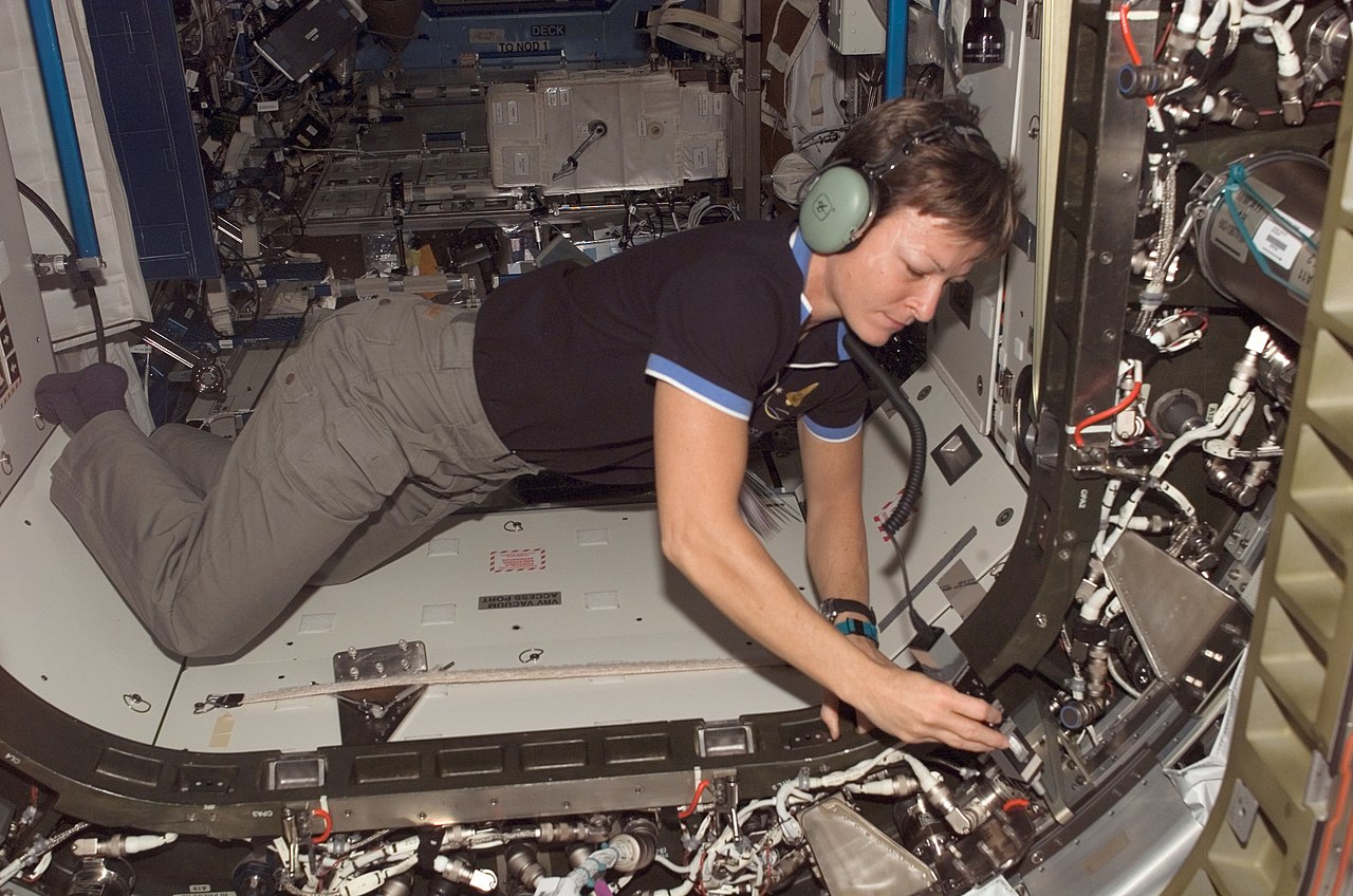


.jpg/1280px-ISS-47_BEAM_installation_(1).jpg)


.jpg)