
Двигатель внутреннего сгорания ( ДВС или двигатель внутреннего сгорания ) — это тепловой двигатель , в котором сгорание топлива происходит с окислителем (обычно воздухом) в камере сгорания , которая является неотъемлемой частью контура потока рабочей жидкости . В двигателе внутреннего сгорания расширение газов высокой температуры и высокого давления , образующихся при сгорании, прикладывает прямую силу к некоторому компоненту двигателя. Сила обычно прикладывается к поршням ( поршневой двигатель ), лопаткам турбины ( газовая турбина ), ротору (двигатель Ванкеля) или соплу ( реактивный двигатель ). Эта сила перемещает компонент на расстояние. Этот процесс преобразует химическую энергию в кинетическую энергию , которая используется для приведения в движение, перемещения или питания всего, к чему прикреплен двигатель.
Первый коммерчески успешный двигатель внутреннего сгорания был создан Этьеном Ленуаром около 1860 года, [1] а первый современный двигатель внутреннего сгорания, известный как двигатель Отто , был создан в 1876 году Николаусом Отто . Термин двигатель внутреннего сгорания обычно относится к двигателю, в котором сгорание является прерывистым , например, более знакомые двухтактные и четырехтактные поршневые двигатели, а также их варианты, такие как шеститактный поршневой двигатель и роторный двигатель Ванкеля . Второй класс двигателей внутреннего сгорания использует непрерывное сгорание: газовые турбины , реактивные двигатели и большинство ракетных двигателей , каждый из которых является двигателем внутреннего сгорания на том же принципе, что и описанный ранее. [1] [2] ( Огнестрельное оружие также является формой двигателя внутреннего сгорания, [2] хотя и настолько специализированного типа, что его обычно рассматривают как отдельную категорию, наряду с таким оружием, как минометы и зенитные пушки.) Напротив, в двигателях внешнего сгорания , таких как паровые или двигатели Стирлинга , энергия подается в рабочую жидкость, не состоящую из продуктов сгорания, не смешанную с ними и не загрязненную ими. Рабочие жидкости для двигателей внешнего сгорания включают воздух, горячую воду, воду под давлением или даже жидкий натрий , нагреваемый в котле .
Хотя существует множество стационарных применений, большинство ДВС используются в мобильных приложениях и являются основным источником питания для транспортных средств, таких как автомобили , самолеты и лодки . ДВС обычно работают на углеводородном топливе, таком как природный газ , бензин , дизельное топливо или этанол . Возобновляемое топливо , такое как биодизель, используется в двигателях с воспламенением от сжатия (CI), а биоэтанол или ЭТБЭ (этил-трет-бутиловый эфир), производимый из биоэтанола, — в двигателях с искровым зажиганием (SI). Еще в 1900 году изобретатель дизельного двигателя Рудольф Дизель использовал арахисовое масло для работы своих двигателей. [3] Возобновляемое топливо обычно смешивают с ископаемым топливом. Водород , который используется редко, можно получить либо из ископаемого топлива, либо из возобновляемой энергии.

Различные ученые и инженеры внесли свой вклад в разработку двигателей внутреннего сгорания. В 1791 году Джон Барбер разработал газовую турбину . В 1794 году Томас Мид запатентовал газовый двигатель . Также в 1794 году Роберт Стрит запатентовал двигатель внутреннего сгорания, который также был первым, использующим жидкое топливо , и построил двигатель примерно в то же время. В 1798 году Джон Стивенс построил первый американский двигатель внутреннего сгорания. В 1807 году французские инженеры Нисефор Ньепс (который впоследствии изобрел фотографию ) и Клод Ньепс запустили прототип двигателя внутреннего сгорания, используя контролируемые взрывы пыли, Pyréolophore , на который Наполеон Бонапарт выдал патент . Этот двигатель приводил в движение лодку на реке Сона во Франции. [4] [5] В том же году швейцарский инженер Франсуа Исаак де Риваз изобрел двигатель внутреннего сгорания на основе водорода и привел двигатель в действие электрической искрой. В 1808 году Де Риваз приспособил свое изобретение к примитивному рабочему транспортному средству – «первому в мире автомобилю с двигателем внутреннего сгорания». [6] В 1823 году Сэмюэл Браун запатентовал первый двигатель внутреннего сгорания, который был применен в промышленности.
В 1854 году в Великобритании итальянские изобретатели Эудженио Барсанти и Феличе Маттеуччи получили сертификат: «Получение движущей силы путем взрыва газов». В 1857 году Патентное ведомство Большой Печати выдало им патент № 1655 на изобретение «Усовершенствованного устройства для получения движущей силы из газов». [7] [8] [9] [10] Барсанти и Маттеуччи получили другие патенты на то же изобретение во Франции, Бельгии и Пьемонте между 1857 и 1859 годами. [11] [12] В 1860 году бельгийский инженер Жан Жозеф Этьен Ленуар создал двигатель внутреннего сгорания, работающий на газе. [13] В 1864 году Николаус Отто запатентовал первый атмосферный газовый двигатель. В 1872 году американец Джордж Брайтон изобрел первый коммерческий двигатель внутреннего сгорания, работающий на жидком топливе. В 1876 году Николаус Отто начал работать с Готлибом Даймлером и Вильгельмом Майбахом , запатентовал сжатый заряд, четырехтактный двигатель. В 1879 году Карл Бенц запатентовал надежный двухтактный бензиновый двигатель. Позже, в 1886 году, Бенц начал первое коммерческое производство автотранспортных средств с двигателем внутреннего сгорания, в котором трехколесный, четырехтактный двигатель и шасси составляли единое целое. [14] В 1892 году Рудольф Дизель разработал первый сжатый заряд, двигатель с воспламенением от сжатия. В 1926 году Роберт Годдард запустил первую ракету на жидком топливе. В 1939 году Heinkel He 178 стал первым в мире реактивным самолетом .
В свое время слово engine (через старофранцузский , от латинского ingenium , «способность») означало любую часть машины — значение, которое сохраняется в таких выражениях, как осадная машина . «Мотор» (от латинского motor , «движитель») — это любая машина, которая производит механическую энергию . Традиционно электродвигатели не называются «двигателями»; однако двигатели внутреннего сгорания часто называют «моторами». ( Электрическим двигателем называют локомотив, работающий от электричества.)
В судоходстве двигатель внутреннего сгорания, установленный в корпусе, называется двигателем, а двигатели, установленные на транце, называются моторами. [15]

Двигатели с возвратно-поступательным движением поршня являются наиболее распространенным источником энергии для наземных и водных транспортных средств , включая автомобили , мотоциклы , корабли и, в меньшей степени, локомотивы (некоторые из них электрические, но большинство используют дизельные двигатели [16] [17] ). Роторные двигатели конструкции Ванкеля используются в некоторых автомобилях, самолетах и мотоциклах. Они известны под общим названием транспортных средств с двигателем внутреннего сгорания (ICEV). [18]
Там, где требуется высокое отношение мощности к весу, двигатели внутреннего сгорания появляются в виде турбин внутреннего сгорания или иногда двигателей Ванкеля. Самолеты с двигателем обычно используют ДВС, который может быть поршневым двигателем. Вместо этого самолеты могут использовать реактивные двигатели , а вертолеты могут использовать турбовальные двигатели ; оба из них являются типами турбин. Помимо обеспечения движения, самолеты могут использовать отдельный ДВС в качестве вспомогательной силовой установки . Двигатели Ванкеля устанавливаются на многих беспилотных летательных аппаратах .
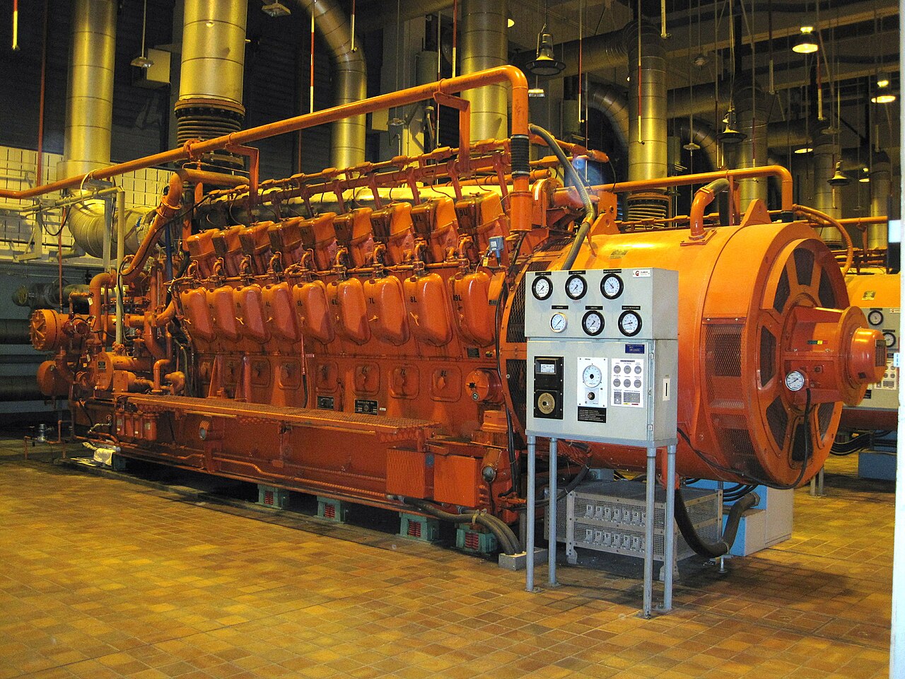
ДВС приводят в действие крупные электрогенераторы, питающие электросети. Они встречаются в виде турбин внутреннего сгорания с типичной электрической мощностью в диапазоне около 100 МВт. Электростанции комбинированного цикла используют высокотемпературные выхлопные газы для кипения и перегрева водяного пара для работы паровой турбины . Таким образом, эффективность выше, поскольку из топлива извлекается больше энергии, чем может быть извлечено одним двигателем внутреннего сгорания. Электростанции комбинированного цикла достигают эффективности в диапазоне 50–60%. В меньших масштабах стационарные двигатели, такие как газовые двигатели или дизельные генераторы, используются для резервного питания или для обеспечения электроэнергией районов, не подключенных к электросети .
Небольшие двигатели (обычно двухтактные бензиновые/бензиновые двигатели) являются распространенным источником энергии для газонокосилок , триммеров , цепных пил , воздуходувок , моек высокого давления , снегоходов , гидроциклов , подвесных лодочных моторов , мопедов и мотоциклов .
Существует несколько возможных способов классификации двигателей внутреннего сгорания.
По количеству ударов:
По типу зажигания:
По механическому/термодинамическому циклу (эти циклы используются нечасто, но обычно встречаются в гибридных автомобилях , а также в других транспортных средствах, произведенных для экономии топлива [20] ):


Основой поршневого двигателя внутреннего сгорания является блок цилиндров , который обычно изготавливается из чугуна (из-за его хорошей износостойкости и низкой стоимости) [22] или алюминия . В последнем случае гильзы цилиндров изготавливаются из чугуна или стали [23] или покрытия, такого как никасил или алюсил . Блок цилиндров содержит цилиндры . В двигателях с более чем одним цилиндром они обычно располагаются либо в 1 ряд ( прямой двигатель ), либо в 2 ряда ( оппозитный двигатель или V-образный двигатель ); в современных двигателях иногда используются 3 или 4 ряда ( двигатель W ), и возможны и использовались другие конфигурации двигателей . Одноцилиндровые двигатели (или thumpers ) распространены для мотоциклов и других небольших двигателей, используемых в легкой технике. На внешней стороне цилиндра в блоке цилиндров отлиты каналы, содержащие охлаждающую жидкость, тогда как в некоторых двигателях большой мощности каналы представляют собой типы съемных гильз цилиндров, которые могут быть заменены. [22] Двигатели с водяным охлаждением содержат каналы в блоке двигателя, где циркулирует охлаждающая жидкость ( водяная рубашка ). Некоторые небольшие двигатели охлаждаются воздухом, и вместо водяной рубашки блок цилиндров имеет ребра, выступающие из него, чтобы охлаждать двигатель путем прямой передачи тепла воздуху. Стенки цилиндров обычно отделываются хонингованием для получения поперечной штриховки , которая способна удерживать больше масла. Слишком грубая поверхность быстро повредит двигатель из-за чрезмерного износа поршня.
Поршни представляют собой короткие цилиндрические детали, которые герметизируют один конец цилиндра от высокого давления сжатого воздуха и продуктов сгорания и непрерывно скользят внутри него во время работы двигателя. В небольших двигателях поршни изготавливаются из алюминия, в то время как в более крупных они обычно изготавливаются из чугуна. [22] В высокопроизводительных приложениях поршни также могут быть из титана или кованой стали для большей прочности. Верхняя поверхность поршня называется его головкой и обычно плоская или вогнутая. В некоторых двухтактных двигателях используются поршни с дефлекторной головкой . Поршни открыты снизу и полые, за исключением встроенной армирующей конструкции (поршневой перемычки). Когда двигатель работает, давление газа в камере сгорания оказывает усилие на головку поршня, которое передается через ее перемычку на поршневой палец . Каждый поршень имеет кольца, установленные по его окружности, которые в основном предотвращают утечку газов в картер или масла в камеру сгорания. [24] Система вентиляции выводит небольшое количество газа, которое выходит мимо поршней во время нормальной работы (картерные газы), из картера, так что он не скапливается, загрязняя масло и вызывая коррозию. [22] В двухтактных бензиновых двигателях картер является частью топливовоздушного тракта, и из-за его непрерывного потока двухтактным двигателям не нужна отдельная система вентиляции картера.

Головка цилиндра крепится к блоку двигателя многочисленными болтами или шпильками . Она имеет несколько функций. Головка цилиндра герметизирует цилиндры со стороны, противоположной поршням; она содержит короткие каналы ( порты ) для впуска и выпуска и соответствующие впускные клапаны , которые открываются, чтобы цилиндр был заполнен свежим воздухом, и выпускные клапаны, которые открываются, чтобы выпустить газы сгорания. Клапаны часто представляют собой тарельчатые клапаны [25] [26], но они также могут быть поворотными клапанами [27] или золотниковыми клапанами . [28] Однако двухтактные двигатели с продувкой картера соединяют газовые порты непосредственно со стенкой цилиндра без тарельчатых клапанов; вместо этого поршень управляет их открытием и закрытием. Головка цилиндра также удерживает свечу зажигания в случае двигателей с искровым зажиганием и инжектор для двигателей, которые используют прямой впрыск. Все двигатели CI (воспламенение от сжатия) используют впрыск топлива, обычно прямой впрыск, но некоторые двигатели вместо этого используют непрямой впрыск . Двигатели SI (искровое зажигание) могут использовать карбюратор или впрыск топлива в качестве впрыска во впускной канал или непосредственного впрыска . Большинство двигателей SI имеют одну свечу зажигания на цилиндр, но некоторые имеют 2. Прокладка головки предотвращает утечку газа между головкой цилиндра и блоком двигателя. Открытие и закрытие клапанов контролируется одним или несколькими распределительными валами и пружинами — или в некоторых двигателях — десмодромным механизмом , который не использует пружины. Распределительный вал может напрямую нажимать на шток клапана или может воздействовать на коромысло , опять же, либо напрямую, либо через толкатель .

Картер герметизирован снизу поддоном , который собирает падающее масло во время нормальной работы для повторного цикла. В полости, образованной между блоком цилиндров и поддоном, находится коленчатый вал , который преобразует возвратно-поступательное движение поршней во вращательное движение. Коленчатый вал удерживается на месте относительно блока двигателя коренными подшипниками , которые позволяют ему вращаться. Переборки в картере образуют половину каждого коренного подшипника; другая половина представляет собой съемную крышку. В некоторых случаях используется одна основная палуба подшипника вместо нескольких меньших крышек. Шатун соединен со смещенными секциями коленчатого вала ( шатунными шейками ) на одном конце и с поршнем на другом конце через поршневой палец и, таким образом, передает усилие и преобразует возвратно-поступательное движение поршней в круговое движение коленчатого вала. Конец шатуна, прикрепленный к поршневому пальцу, называется его малым концом, а другой конец, где он соединен с коленчатым валом, большим концом. Большая головка имеет съемную половину, позволяющую сборку вокруг коленчатого вала. Она крепится к шатуну съемными болтами.
Головка блока цилиндров имеет впускной коллектор и выпускной коллектор, прикрепленные к соответствующим портам. Впускной коллектор подключается непосредственно к воздушному фильтру или к карбюратору, если он имеется, который затем подключается к воздушному фильтру . Он распределяет поступающий из этих устройств воздух по отдельным цилиндрам. Выпускной коллектор является первым компонентом в выхлопной системе . Он собирает выхлопные газы из цилиндров и направляет их к следующему компоненту на пути. Выхлопная система ДВС может также включать каталитический нейтрализатор и глушитель . Конечным участком на пути выхлопных газов является выхлопная труба .

Верхняя мертвая точка (ВМТ) поршня — это положение, в котором он находится ближе всего к клапанам; нижняя мертвая точка (НМТ) — это противоположное положение, в котором он находится дальше всего от них. Ход — это движение поршня от ВМТ к НМТ или наоборот вместе с сопутствующим процессом. Во время работы двигателя коленчатый вал непрерывно вращается с почти постоянной скоростью . В 4-тактном ДВС каждый поршень совершает 2 хода за один оборот коленчатого вала в следующем порядке. Начиная описание с ВМТ, это: [29] [30]
Определяющей характеристикой этого типа двигателя является то, что каждый поршень завершает цикл за каждый оборот коленчатого вала. 4 процесса впуска, сжатия, мощности и выпуска происходят всего за 2 такта, так что невозможно выделить такт исключительно для каждого из них. Начиная с ВМТ цикл состоит из:
В то время как 4-тактный двигатель использует поршень как насос прямого вытеснения для выполнения продувки, используя 2 из 4 тактов, 2-тактный двигатель использует последнюю часть рабочего хода и первую часть такта сжатия для комбинированного впуска и выпуска. Работа, необходимая для вытеснения заряда и выхлопных газов, выполняется либо картером, либо отдельным нагнетателем. Для продувки, вытеснения сгоревшего газа и ввода свежей смеси описаны два основных подхода: продувка контуром и продувка однопоточным способом. Новости SAE, опубликованные в 2010-х годах, говорят о том, что «продувка контуром» лучше при любых обстоятельствах, чем продувка однопоточным способом. [19]
Некоторые двигатели SI продуваются картером и не используют тарельчатые клапаны. Вместо этого картер и часть цилиндра под поршнем используются в качестве насоса. Впускной порт соединен с картером через пластинчатый клапан или поворотный дисковый клапан, приводимый в действие двигателем. Для каждого цилиндра порт передачи одним концом соединяется с картером, а другим концом — со стенкой цилиндра. Выпускной порт соединен непосредственно со стенкой цилиндра. Порт передачи и выпускной порт открываются и закрываются поршнем. Пластинчатый клапан открывается, когда давление в картере немного ниже давления впуска, чтобы позволить ему наполниться новым зарядом; это происходит, когда поршень движется вверх. Когда поршень движется вниз, давление в картере увеличивается, и пластинчатый клапан быстро закрывается, затем заряд в картере сжимается. Когда поршень движется вниз, он также открывает выпускной порт и порт передачи, и более высокое давление заряда в картере заставляет его поступать в цилиндр через порт передачи, выдувая выхлопные газы. Смазка осуществляется путем добавления двухтактного масла в топливо в небольших пропорциях. Petroil относится к смеси бензина с вышеупомянутым маслом. Этот тип двухтактного двигателя имеет более низкую эффективность, чем сопоставимые четырехтактные двигатели, и выделяет больше загрязняющих выхлопных газов при следующих условиях:
Главным преимуществом двухтактных двигателей этого типа является механическая простота и более высокое отношение мощности к весу, чем у их четырехтактных аналогов. Несмотря на то, что на цикл приходится в два раза больше рабочих тактов, на практике достижима мощность менее чем в два раза больше мощности сопоставимого четырехтактного двигателя.
В США двухтактные двигатели были запрещены для дорожных транспортных средств из-за загрязнения. Мотоциклы, предназначенные только для бездорожья, по-прежнему часто имеют двухтактные двигатели, но редко разрешены для использования на дорогах общего пользования. Тем не менее, используются тысячи двухтактных двигателей для ухода за газонами. [ необходима цитата ]

Использование отдельного нагнетателя позволяет избежать многих недостатков продувки картера за счет увеличения сложности, что означает более высокую стоимость и увеличение требований к техническому обслуживанию. Двигатель этого типа использует порты или клапаны для впуска и клапаны для выпуска, за исключением двигателей с оппозитными поршнями , которые также могут использовать порты для выпуска. Нагнетатель обычно типа Roots, но использовались и другие типы. Такая конструкция является обычной в двигателях CI и иногда использовалась в двигателях SI.
Двигатели с воспламенением от сжатия, в которых используется нагнетатель, обычно используют прямоточную продувку . В этой конструкции стенка цилиндра содержит несколько впускных отверстий, равномерно расположенных по окружности чуть выше положения, которого достигает головка поршня в НМТ. Используется выпускной клапан или несколько, как в 4-тактных двигателях. Конечная часть впускного коллектора представляет собой воздушный рукав, который питает впускные отверстия. Впускные отверстия расположены под горизонтальным углом к стенке цилиндра (т. е. они находятся в плоскости головки поршня), чтобы придать вихрь входящему заряду для улучшения сгорания. Самыми большими поршневыми двигателями с воспламенением от сжатия являются низкооборотные двигатели с воспламенением от сжатия этого типа; они используются для морского движения (см. морской дизельный двигатель ) или выработки электроэнергии и достигают наивысшей тепловой эффективности среди двигателей внутреннего сгорания любого типа. Некоторые двигатели дизель-электрических локомотивов работают по двухтактному циклу. Самые мощные из них имеют тормозную мощность около 4,5 МВт или 6000 л. с . Примером такого класса являются локомотивы класса EMD SD90MAC. Сопоставимый класс GE AC6000CW , чей первичный двигатель имеет почти такую же тормозную мощность, использует 4-тактный двигатель.
Примером такого типа двигателя является двухтактный дизельный двигатель с турбонаддувом Wärtsilä-Sulzer RTA96-C , используемый на крупных контейнеровозах. Это самый эффективный и мощный поршневой двигатель внутреннего сгорания в мире с термическим КПД более 50%. [31] [32] [33] Для сравнения, самые эффективные малые четырехтактные двигатели имеют термический КПД около 43% (SAE 900648); [ требуется ссылка ] размер является преимуществом для эффективности из-за увеличения отношения объема к площади поверхности.
По внешним ссылкам можно посмотреть видео о сгорании топлива в цилиндре двухтактного оптически доступного двигателя мотоцикла.
Дугалд Клерк разработал первый двухтактный двигатель в 1879 году. Он использовал отдельный цилиндр, который функционировал как насос для перекачивания топливной смеси в цилиндр. [19]
В 1899 году Джон Дэй упростил конструкцию Клерка до типа двухтактного двигателя, который очень широко используется сегодня. [34] Двигатели с циклом Дэй имеют продувку картера и синхронизацию портов. Картер и часть цилиндра под выпускным портом используются в качестве насоса. Работа двигателя с циклом Дэй начинается, когда коленчатый вал поворачивается так, что поршень движется от НМТ вверх (к головке), создавая вакуум в области картера/цилиндра. Затем карбюратор подает топливную смесь в картер через пластинчатый клапан или поворотный дисковый клапан (приводимый в действие двигателем). От картера к порту в цилиндре отлиты каналы, обеспечивающие впуск, и еще один от выпускного порта к выхлопной трубе. Высота порта по отношению к длине цилиндра называется «синхронизацией порта».
При первом ходе двигателя вверх топливо не будет всасываться в цилиндр, так как картер будет пуст. При ходе вниз поршень теперь сжимает топливную смесь, которая смазала поршень в цилиндре и подшипники из-за того, что в топливную смесь было добавлено масло. Когда поршень движется вниз, он сначала открывает выхлоп, но при первом ходе нет сгоревшего топлива для выпуска. Когда поршень движется дальше вниз, он открывает впускной порт, который имеет канал, идущий к картеру. Поскольку топливная смесь в картере находится под давлением, смесь движется через канал в цилиндр.
Поскольку в цилиндре нет препятствий для прямого выхода топлива из выпускного отверстия до того, как поршень поднимется достаточно высоко, чтобы закрыть отверстие, в ранних двигателях использовался высокий куполообразный поршень для замедления потока топлива. Позже топливо «резонировало» обратно в цилиндр с помощью конструкции расширительной камеры. Когда поршень поднимался близко к ВМТ, искра воспламеняла топливо. Когда поршень движется вниз под действием силы, он сначала открывает выпускное отверстие, где сгоревшее топливо выбрасывается под высоким давлением, а затем впускное отверстие, где процесс был завершен и будет продолжать повторяться.
Более поздние двигатели использовали тип портирования, разработанный компанией Deutz для улучшения производительности. Он назывался Schnurle Reverse Flow system. DKW лицензировала эту конструкцию для всех своих мотоциклов. Их DKW RT 125 был одним из первых транспортных средств, достигших в результате более 100 миль на галлон. [35]
Двигатели внутреннего сгорания требуют воспламенения смеси либо искровым зажиганием (SI) , либо воспламенением от сжатия (CI) . До изобретения надежных электрических методов использовались методы горячей трубы и пламени. Были построены экспериментальные двигатели с лазерным зажиганием . [36]

Двигатель с искровым зажиганием был усовершенствованием ранних двигателей, которые использовали зажигание Hot Tube. Когда Bosch разработал магнето, оно стало основной системой для производства электроэнергии для питания свечи зажигания. [37] Во многих небольших двигателях до сих пор используется зажигание от магнето. Небольшие двигатели запускаются вручную с помощью стартера с ручным приводом или рукоятки. До разработки Чарльзом Ф. Кеттерингом из Delco автомобильного стартера все автомобили с бензиновым двигателем использовали рукоятку. [38]
Более крупные двигатели обычно питают свои пусковые двигатели и системы зажигания , используя электрическую энергию, хранящуюся в свинцово-кислотной батарее . Заряженное состояние батареи поддерживается автомобильным генератором или (ранее) генератором, который использует мощность двигателя для создания хранилища электроэнергии.
Аккумуляторная батарея обеспечивает электроэнергию для запуска, когда двигатель имеет систему пускового двигателя , и обеспечивает электроэнергию, когда двигатель выключен. Аккумуляторная батарея также обеспечивает электроэнергию в редких условиях работы, когда генератор не может поддерживать более 13,8 вольт (для обычной автомобильной электрической системы 12 В). Когда напряжение генератора падает ниже 13,8 вольт, свинцово-кислотная аккумуляторная батарея все больше принимает на себя электрическую нагрузку. Практически во всех условиях работы, включая нормальные условия холостого хода, генератор обеспечивает первичную электроэнергию.
Некоторые системы отключают питание поля генератора (ротора) при полностью открытой дроссельной заслонке. Отключение поля снижает механическую нагрузку шкива генератора почти до нуля, максимизируя мощность коленчатого вала. В этом случае аккумулятор поставляет всю первичную электроэнергию.
Бензиновые двигатели всасывают смесь воздуха и бензина и сжимают ее движением поршня от нижней мертвой точки до верхней мертвой точки, когда топливо находится в состоянии максимального сжатия. Уменьшение размера рабочей поверхности цилиндра и учет объема камеры сгорания описываются соотношением. Ранние двигатели имели степень сжатия 6 к 1. С увеличением степени сжатия эффективность двигателя также увеличивалась.
С ранними системами индукции и зажигания степень сжатия приходилось поддерживать низкой. С достижениями в топливной технологии и управлении сгоранием высокопроизводительные двигатели могут надежно работать при соотношении 12:1. С низкооктановым топливом возникала проблема, поскольку степень сжатия увеличивалась по мере воспламенения топлива из-за повышения температуры, которое возникало в результате. Чарльз Кеттеринг разработал свинцовую добавку , которая позволяла добиться более высоких степеней сжатия, от которой постепенно отказывались в автомобильной промышленности с 1970-х годов, отчасти из-за проблем с отравлением свинцом .
Топливная смесь воспламеняется при разных перемещениях поршня в цилиндре. При низких оборотах искра синхронизируется так, чтобы она возникла близко к достижению поршнем верхней мертвой точки. Для того, чтобы вырабатывать больше мощности, по мере увеличения оборотов искра продвигается вперед раньше во время движения поршня. Искра возникает, когда топливо все еще сжимается все больше и больше по мере увеличения оборотов. [39]
Необходимое высокое напряжение, обычно 10 000 вольт, подается индукционной катушкой или трансформатором. Индукционная катушка представляет собой систему обратного хода, использующую прерывание тока первичной электрической системы через некоторый тип синхронизированного прерывателя. Прерывателем могут быть как контактные точки, так и силовой транзистор. Проблема с этим типом зажигания заключается в том, что с ростом оборотов в минуту доступность электрической энергии уменьшается. Это особенно проблема, поскольку количество энергии, необходимое для воспламенения более плотной топливной смеси, выше. Результатом часто были пропуски зажигания на высоких оборотах в минуту.
Было разработано зажигание с разрядом конденсатора . Оно создает нарастающее напряжение, которое подается на свечу зажигания. Напряжение в системе CD может достигать 60 000 вольт. [40] В системах зажигания CD используются повышающие трансформаторы . Повышающий трансформатор использует энергию, накопленную в емкости, для генерации электрической искры . В любой из систем механическая или электрическая система управления обеспечивает тщательно рассчитанное высокое напряжение для соответствующего цилиндра. Эта искра через свечу зажигания воспламеняет воздушно-топливную смесь в цилиндрах двигателя.
Хотя бензиновые двигатели внутреннего сгорания гораздо легче запускаются в холодную погоду, чем дизельные, у них все еще могут быть проблемы с запуском в холодную погоду в экстремальных условиях. В течение многих лет решением было парковать автомобиль в отапливаемых помещениях. В некоторых частях мира масло фактически сливали и нагревали в течение ночи и возвращали в двигатель для холодного запуска. В начале 1950-х годов был разработан блок бензинового газификатора, в котором при запуске в холодную погоду сырой бензин направлялся в блок, где часть топлива сжигалась, заставляя другую часть превращаться в горячий пар, направляемый непосредственно во впускной клапанный коллектор. Этот блок был довольно популярен, пока электрические нагреватели блока цилиндров не стали стандартными для бензиновых двигателей, продаваемых в холодном климате. [41]
Для зажигания дизельные, PPC и HCCI двигатели полагаются исключительно на высокую температуру и давление, создаваемые двигателем в процессе сжатия. Уровень сжатия, который возникает, обычно в два раза или больше, чем у бензинового двигателя. Дизельные двигатели всасывают только воздух и незадолго до пикового сжатия впрыскивают небольшое количество дизельного топлива в цилиндр через топливный инжектор, который позволяет топливу мгновенно воспламениться. Двигатели типа HCCI всасывают как воздух, так и топливо, но продолжают полагаться на процесс самовоспламенения без посторонней помощи из-за более высоких давлений и температуры. Вот почему дизельные и HCCI двигатели более подвержены проблемам с холодным запуском, хотя они работают так же хорошо в холодную погоду после запуска. Легковые дизельные двигатели с непрямым впрыском в автомобилях и легких грузовиках используют свечи накаливания (или другой предварительный нагрев: см. Cummins ISB#6BT ), которые предварительно нагревают камеру сгорания непосредственно перед запуском, чтобы уменьшить условия отсутствия запуска в холодную погоду. Большинство дизелей также имеют аккумулятор и систему зарядки; Тем не менее, эта система является вторичной и добавляется производителями как роскошь для простоты запуска, включения и выключения подачи топлива (что также может быть сделано с помощью переключателя или механического устройства), а также для работы вспомогательных электрических компонентов и аксессуаров. Большинство новых двигателей используют электрические и электронные блоки управления двигателем (ЭБУ), которые также регулируют процесс сгорания для повышения эффективности и снижения выбросов.
.jpg/1280px-Overhead_cam_engine_with_forced_oil_lubrication_(Autocar_Handbook,_13th_ed,_1935).jpg)
Surfaces in contact and relative motion to other surfaces require lubrication to reduce wear, noise and increase efficiency by reducing the power wasting in overcoming friction, or to make the mechanism work at all. Also, the lubricant used can reduce excess heat and provide additional cooling to components. At the very least, an engine requires lubrication in the following parts:
In 2-stroke crankcase scavenged engines, the interior of the crankcase, and therefore the crankshaft, connecting rod and bottom of the pistons are sprayed by the two-stroke oil in the air-fuel-oil mixture which is then burned along with the fuel. The valve train may be contained in a compartment flooded with lubricant so that no oil pump is required.
In a splash lubrication system no oil pump is used. Instead the crankshaft dips into the oil in the sump and due to its high speed, it splashes the crankshaft, connecting rods and bottom of the pistons. The connecting rod big end caps may have an attached scoop to enhance this effect. The valve train may also be sealed in a flooded compartment, or open to the crankshaft in a way that it receives splashed oil and allows it to drain back to the sump. Splash lubrication is common for small 4-stroke engines.
In a forced (also called pressurized) lubrication system, lubrication is accomplished in a closed-loop which carries motor oil to the surfaces serviced by the system and then returns the oil to a reservoir. The auxiliary equipment of an engine is typically not serviced by this loop; for instance, an alternator may use ball bearings sealed with their own lubricant. The reservoir for the oil is usually the sump, and when this is the case, it is called a wet sump system. When there is a different oil reservoir the crankcase still catches it, but it is continuously drained by a dedicated pump; this is called a dry sump system.
On its bottom, the sump contains an oil intake covered by a mesh filter which is connected to an oil pump then to an oil filter outside the crankcase. From there it is diverted to the crankshaft main bearings and valve train. The crankcase contains at least one oil gallery (a conduit inside a crankcase wall) to which oil is introduced from the oil filter. The main bearings contain a groove through all or half its circumference; the oil enters these grooves from channels connected to the oil gallery. The crankshaft has drillings that take oil from these grooves and deliver it to the big end bearings. All big end bearings are lubricated this way. A single main bearing may provide oil for 0, 1 or 2 big end bearings. A similar system may be used to lubricate the piston, its gudgeon pin and the small end of its connecting rod; in this system, the connecting rod big end has a groove around the crankshaft and a drilling connected to the groove which distributes oil from there to the bottom of the piston and from then to the cylinder.
Other systems are also used to lubricate the cylinder and piston. The connecting rod may have a nozzle to throw an oil jet to the cylinder and bottom of the piston. That nozzle is in movement relative to the cylinder it lubricates, but always pointed towards it or the corresponding piston.
Typically forced lubrication systems have a lubricant flow higher than what is required to lubricate satisfactorily, in order to assist with cooling. Specifically, the lubricant system helps to move heat from the hot engine parts to the cooling liquid (in water-cooled engines) or fins (in air-cooled engines) which then transfer it to the environment. The lubricant must be designed to be chemically stable and maintain suitable viscosities within the temperature range it encounters in the engine.
Common cylinder configurations include the straight or inline configuration, the more compact V configuration, and the wider but smoother flat or boxer configuration. Aircraft engines can also adopt a radial configuration, which allows more effective cooling. More unusual configurations such as the H, U, X, and W have also been used.

Multiple cylinder engines have their valve train and crankshaft configured so that pistons are at different parts of their cycle. It is desirable to have the pistons' cycles uniformly spaced (this is called even firing) especially in forced induction engines; this reduces torque pulsations[42] and makes inline engines with more than 3 cylinders statically balanced in its primary forces. However, some engine configurations require odd firing to achieve better balance than what is possible with even firing. For instance, a 4-stroke I2 engine has better balance when the angle between the crankpins is 180° because the pistons move in opposite directions and inertial forces partially cancel, but this gives an odd firing pattern where one cylinder fires 180° of crankshaft rotation after the other, then no cylinder fires for 540°. With an even firing pattern, the pistons would move in unison and the associated forces would add.
Multiple crankshaft configurations do not necessarily need a cylinder head at all because they can instead have a piston at each end of the cylinder called an opposed piston design. Because fuel inlets and outlets are positioned at opposed ends of the cylinder, one can achieve uniflow scavenging, which, as in the four-stroke engine is efficient over a wide range of engine speeds. Thermal efficiency is improved because of a lack of cylinder heads. This design was used in the Junkers Jumo 205 diesel aircraft engine, using two crankshafts at either end of a single bank of cylinders, and most remarkably in the Napier Deltic diesel engines. These used three crankshafts to serve three banks of double-ended cylinders arranged in an equilateral triangle with the crankshafts at the corners. It was also used in single-bank locomotive engines, and is still used in marine propulsion engines and marine auxiliary generators.

Most truck and automotive diesel engines use a cycle reminiscent of a four-stroke cycle, but with temperature increase by compression causing ignition, rather than needing a separate ignition system. This variation is called the diesel cycle. In the diesel cycle, diesel fuel is injected directly into the cylinder so that combustion occurs at constant pressure, as the piston moves.
The Otto cycle is the most common cycle for most cars' internal combustion engines that use gasoline as a fuel. It consists of the same major steps as described for the four-stroke engine: Intake, compression, ignition, expansion and exhaust.
In 1879, Nicolaus Otto manufactured and sold a double expansion engine (the double and triple expansion principles had ample usage in steam engines), with two small cylinders at both sides of a low-pressure larger cylinder, where a second expansion of exhaust stroke gas took place; the owner returned it, alleging poor performance. In 1906, the concept was incorporated in a car built by EHV (Eisenhuth Horseless Vehicle Company);[43] and in the 21st century Ilmor designed and successfully tested a 5-stroke double expansion internal combustion engine, with high power output and low SFC (Specific Fuel Consumption).[44]
The six-stroke engine was invented in 1883. Four kinds of six-stroke engines use a regular piston in a regular cylinder (Griffin six-stroke, Bajulaz six-stroke, Velozeta six-stroke and Crower six-stroke), firing every three crankshaft revolutions. These systems capture the waste heat of the four-stroke Otto cycle with an injection of air or water.
The Beare Head and "piston charger" engines operate as opposed-piston engines, two pistons in a single cylinder, firing every two revolutions rather than every four like a four-stroke engine.
The first internal combustion engines did not compress the mixture. The first part of the piston downstroke drew in a fuel-air mixture, then the inlet valve closed and, in the remainder of the down-stroke, the fuel-air mixture fired. The exhaust valve opened for the piston upstroke. These attempts at imitating the principle of a steam engine were very inefficient. There are a number of variations of these cycles, most notably the Atkinson and Miller cycles.
Split-cycle engines separate the four strokes of intake, compression, combustion and exhaust into two separate but paired cylinders. The first cylinder is used for intake and compression. The compressed air is then transferred through a crossover passage from the compression cylinder into the second cylinder, where combustion and exhaust occur. A split-cycle engine is really an air compressor on one side with a combustion chamber on the other.
Previous split-cycle engines have had two major problems—poor breathing (volumetric efficiency) and low thermal efficiency. However, new designs are being introduced that seek to address these problems. The Scuderi Engine addresses the breathing problem by reducing the clearance between the piston and the cylinder head through various turbocharging techniques. The Scuderi design requires the use of outwardly opening valves that enable the piston to move very close to the cylinder head without the interference of the valves. Scuderi addresses the low thermal efficiency via firing after top dead center (ATDC).
Firing ATDC can be accomplished by using high-pressure air in the transfer passage to create sonic flow and high turbulence in the power cylinder.

Jet engines use a number of rows of fan blades to compress air which then enters a combustor where it is mixed with fuel (typically JP fuel) and then ignited. The burning of the fuel raises the temperature of the air which is then exhausted out of the engine creating thrust. A modern turbofan engine can operate at as high as 48% efficiency.[45]
There are six sections to a turbofan engine:

A gas turbine compresses air and uses it to turn a turbine. It is essentially a jet engine which directs its output to a shaft. There are three stages to a turbine: 1) air is drawn through a compressor where the temperature rises due to compression, 2) fuel is added in the combuster, and 3) hot air is exhausted through turbine blades which rotate a shaft connected to the compressor.
A gas turbine is a rotary machine similar in principle to a steam turbine and it consists of three main components: a compressor, a combustion chamber, and a turbine. The temperature of the air, after being compressed in the compressor, is increased by burning fuel in it. The heated air and the products of combustion expand in a turbine, producing work output. About 2⁄3 of the work drives the compressor: the rest (about 1⁄3) is available as useful work output.[47]
Gas turbines are among the most efficient internal combustion engines. The General Electric 7HA and 9HA turbine combined cycle electrical plants are rated at over 61% efficiency.[48]
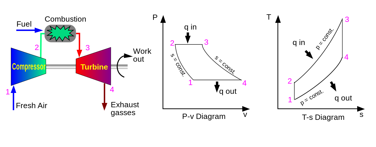
A gas turbine is a rotary machine somewhat similar in principle to a steam turbine. It consists of three main components: compressor, combustion chamber, and turbine. The air is compressed by the compressor where a temperature rise occurs. The temperature of the compressed air is further increased by combustion of injected fuel in the combustion chamber which expands the air. This energy rotates the turbine which powers the compressor via a mechanical coupling. The hot gases are then exhausted to provide thrust.
Gas turbine cycle engines employ a continuous combustion system where compression, combustion, and expansion occur simultaneously at different places in the engine—giving continuous power. Notably, the combustion takes place at constant pressure, rather than with the Otto cycle, constant volume.

The Wankel engine (rotary engine) does not have piston strokes. It operates with the same separation of phases as the four-stroke engine with the phases taking place in separate locations in the engine. In thermodynamic terms it follows the Otto engine cycle, so may be thought of as a "four-phase" engine. While it is true that three power strokes typically occur per rotor revolution, due to the 3:1 revolution ratio of the rotor to the eccentric shaft, only one power stroke per shaft revolution actually occurs. The drive (eccentric) shaft rotates once during every power stroke instead of twice (crankshaft), as in the Otto cycle, giving it a greater power-to-weight ratio than piston engines. This type of engine was most notably used in the Mazda RX-8, the earlier RX-7, and other vehicle models. The engine is also used in unmanned aerial vehicles, where the small size and weight and the high power-to-weight ratio are advantageous.
Forced induction is the process of delivering compressed air to the intake of an internal combustion engine. A forced induction engine uses a gas compressor to increase the pressure, temperature and density of the air. An engine without forced induction is considered a naturally aspirated engine.
Forced induction is used in the automotive and aviation industry to increase engine power and efficiency. It particularly helps aviation engines, as they need to operate at high altitude.
Forced induction is achieved by a supercharger, where the compressor is directly powered from the engine shaft or, in the turbocharger, from a turbine powered by the engine exhaust.
All internal combustion engines depend on combustion of a chemical fuel, typically with oxygen from the air (though it is possible to inject nitrous oxide to do more of the same thing and gain a power boost). The combustion process typically results in the production of a great quantity of thermal energy, as well as the production of steam and carbon dioxide and other chemicals at very high temperature; the temperature reached is determined by the chemical make up of the fuel and oxidizers (see stoichiometry), as well as by the compression and other factors.
The most common modern fuels are made up of hydrocarbons and are derived mostly from fossil fuels (petroleum). Fossil fuels include diesel fuel, gasoline and petroleum gas, and the rarer use of propane. Except for the fuel delivery components, most internal combustion engines that are designed for gasoline use can run on natural gas or liquefied petroleum gases without major modifications. Large diesels can run with air mixed with gases and a pilot diesel fuel ignition injection. Liquid and gaseous biofuels, such as ethanol and biodiesel (a form of diesel fuel that is produced from crops that yield triglycerides such as soybean oil), can also be used. Engines with appropriate modifications can also run on hydrogen gas, wood gas, or charcoal gas, as well as from so-called producer gas made from other convenient biomass. Experiments have also been conducted using powdered solid fuels, such as the magnesium injection cycle.
Presently, fuels used include:
Even fluidized metal powders and explosives have seen some use. Engines that use gases for fuel are called gas engines and those that use liquid hydrocarbons are called oil engines; however, gasoline engines are also often colloquially referred to as "gas engines" ("petrol engines" outside North America).
The main limitations on fuels are that it must be easily transportable through the fuel system to the combustion chamber, and that the fuel releases sufficient energy in the form of heat upon combustion to make practical use of the engine.
Diesel engines are generally heavier, noisier, and more powerful at lower speeds than gasoline engines. They are also more fuel-efficient in most circumstances and are used in heavy road vehicles, some automobiles (increasingly so for their increased fuel efficiency over gasoline engines), ships, railway locomotives, and light aircraft. Gasoline engines are used in most other road vehicles including most cars, motorcycles, and mopeds. In Europe, sophisticated diesel-engined cars have taken over about 45% of the market since the 1990s. There are also engines that run on hydrogen, methanol, ethanol, liquefied petroleum gas (LPG), biodiesel, paraffin and tractor vaporizing oil (TVO).
Hydrogen could eventually replace conventional fossil fuels in traditional internal combustion engines. Alternatively fuel cell technology may come to deliver its promise and the use of the internal combustion engines could even be phased out.
Although there are multiple ways of producing free hydrogen, those methods require converting combustible molecules into hydrogen or consuming electric energy. Unless that electricity is produced from a renewable source—and is not required for other purposes—hydrogen does not solve any energy crisis. In many situations the disadvantage of hydrogen, relative to carbon fuels, is its storage. Liquid hydrogen has extremely low density (14 times lower than water) and requires extensive insulation—whilst gaseous hydrogen requires heavy tankage. Even when liquefied, hydrogen has a higher specific energy but the volumetric energetic storage is still roughly five times lower than gasoline. However, the energy density of hydrogen is considerably higher than that of electric batteries, making it a serious contender as an energy carrier to replace fossil fuels. The 'Hydrogen on Demand' process (see direct borohydride fuel cell) creates hydrogen as needed, but has other issues, such as the high price of the sodium borohydride that is the raw material.

Since air is plentiful at the surface of the earth, the oxidizer is typically atmospheric oxygen, which has the advantage of not being stored within the vehicle. This increases the power-to-weight and power-to-volume ratios. Other materials are used for special purposes, often to increase power output or to allow operation under water or in space.
Cooling is required to remove excessive heat—high temperature can cause engine failure, usually from wear (due to high-temperature-induced failure of lubrication), cracking or warping. Two most common forms of engine cooling are air-cooled and water-cooled. Most modern automotive engines are both water and air-cooled, as the water/liquid-coolant is carried to air-cooled fins and/or fans, whereas larger engines may be singularly water-cooled as they are stationary and have a constant supply of water through water-mains or fresh-water, while most power tool engines and other small engines are air-cooled. Some engines (air or water-cooled) also have an oil cooler. In some engines, especially for turbine engine blade cooling and liquid rocket engine cooling, fuel is used as a coolant, as it is simultaneously preheated before injecting it into a combustion chamber.

Internal combustion engines must have their cycles started. In reciprocating engines this is accomplished by turning the crankshaft (Wankel Rotor Shaft) which induces the cycles of intake, compression, combustion, and exhaust. The first engines were started with a turn of their flywheels, while the first vehicle (the Daimler Reitwagen) was started with a hand crank. All ICE engined automobiles were started with hand cranks until Charles Kettering developed the electric starter for automobiles.[51] This method is now the most widely used, even among non-automobiles.
As diesel engines have become larger and their mechanisms heavier, air starters have come into use.[52] This is due to the lack of torque in electric starters. Air starters work by pumping compressed air into the cylinders of an engine to start it turning.
Two-wheeled vehicles may have their engines started in one of four ways:
There are also starters where a spring is compressed by a crank motion and then used to start an engine.
Some small engines use a pull-rope mechanism called "recoil starting", as the rope rewinds itself after it has been pulled out to start the engine. This method is commonly used in pushed lawn mowers and other settings where only a small amount of torque is needed to turn an engine over.
Turbine engines are frequently started by an electric motor or by compressed air.
Engine types vary greatly in a number of different ways:
Once ignited and burnt, the combustion products—hot gases—have more available thermal energy than the original compressed fuel-air mixture (which had higher chemical energy). This available energy is manifested as a higher temperature and pressure that can be converted into kinetic energy by the engine. In a reciprocating engine, the high-pressure gases inside the cylinders drive the engine's pistons.
Once the available energy has been removed, the remaining hot gases are vented (often by opening a valve or exposing the exhaust outlet) and this allows the piston to return to its previous position (top dead center, or TDC). The piston can then proceed to the next phase of its cycle, which varies between engines. Any thermal energy that is not translated into work is normally considered a waste product and is removed from the engine either by an air or liquid cooling system.
Internal combustion engines are considered heat engines (since the release of chemical energy in combustion has the same effect as heat transfer into the engine) and as such their theoretical efficiency can be approximated by idealized thermodynamic cycles. The thermal efficiency of a theoretical cycle cannot exceed that of the Carnot cycle, whose efficiency is determined by the difference between the lower and upper operating temperatures of the engine. The upper operating temperature of an engine is limited by two main factors; the thermal operating limits of the materials, and the auto-ignition resistance of the fuel. All metals and alloys have a thermal operating limit, and there is significant research into ceramic materials that can be made with greater thermal stability and desirable structural properties. Higher thermal stability allows for a greater temperature difference between the lower (ambient) and upper operating temperatures, hence greater thermodynamic efficiency. Also, as the cylinder temperature rises, the fuel becomes more prone to auto-ignition. This is caused when the cylinder temperature nears the flash point of the charge. At this point, ignition can spontaneously occur before the spark plug fires, causing excessive cylinder pressures. Auto-ignition can be mitigated by using fuels with high auto-ignition resistance (octane rating), however it still puts an upper bound on the allowable peak cylinder temperature.
The thermodynamic limits assume that the engine is operating under ideal conditions: a frictionless world, ideal gases, perfect insulators, and operation for infinite time. Real world applications introduce complexities that reduce efficiency. For example, a real engine runs best at a specific load, termed its power band. The engine in a car cruising on a highway is usually operating significantly below its ideal load, because it is designed for the higher loads required for rapid acceleration.[citation needed] In addition, factors such as wind resistance reduce overall system efficiency. Vehicle fuel economy is measured in miles per gallon or in liters per 100 kilometers. The volume of hydrocarbon assumes a standard energy content.
Even when aided with turbochargers and stock efficiency aids, most engines retain an average efficiency of about 18–20%.[53] However, the latest technologies in Formula One engines have seen a boost in thermal efficiency past 50%.[54]There are many inventions aimed at increasing the efficiency of IC engines. In general, practical engines are always compromised by trade-offs between different properties such as efficiency, weight, power, heat, response, exhaust emissions, or noise. Sometimes economy also plays a role in not only the cost of manufacturing the engine itself, but also manufacturing and distributing the fuel. Increasing the engine's efficiency brings better fuel economy but only if the fuel cost per energy content is the same.
For stationary and shaft engines including propeller engines, fuel consumption is measured by calculating the brake specific fuel consumption, which measures the mass flow rate of fuel consumption divided by the power produced.
For internal combustion engines in the form of jet engines, the power output varies drastically with airspeed and a less variable measure is used: thrust specific fuel consumption (TSFC), which is the mass of propellant needed to generate impulses that is measured in either pound force-hour or the grams of propellant needed to generate an impulse that measures one kilonewton-second.
For rockets, TSFC can be used, but typically other equivalent measures are traditionally used, such as specific impulse and effective exhaust velocity.
Internal combustion engines such as reciprocating internal combustion engines produce air pollution emissions, due to incomplete combustion of carbonaceous fuel. The main derivatives of the process are carbon dioxide CO
2, water and some soot—also called particulate matter (PM).[55] The effects of inhaling particulate matter have been studied in humans and animals and include asthma, lung cancer, cardiovascular issues, and premature death.[56] There are, however, some additional products of the combustion process that include nitrogen oxides and sulfur and some uncombusted hydrocarbons, depending on the operating conditions and the fuel-air ratio.
Carbon dioxide emissions from internal combustion engines (particularly ones using fossil fuels such as gasoline and diesel) contribute to human-induced climate change. Increasing the engine's fuel efficiency can reduce, but not eliminate, the amount of CO
2 emissions as carbon-based fuel combustion produces CO
2. Since removing CO
2 from engine exhaust is impractical, there is increasing interest in alternatives. Sustainable fuels such as biofuels, synfuels, and electric motors powered by batteries are examples.
Not all of the fuel is completely consumed by the combustion process. A small amount of fuel is present after combustion, and some of it reacts to form oxygenates, such as formaldehyde or acetaldehyde, or hydrocarbons not originally present in the input fuel mixture. Incomplete combustion usually results from insufficient oxygen to achieve the perfect stoichiometric ratio. The flame is "quenched" by the relatively cool cylinder walls, leaving behind unreacted fuel that is expelled with the exhaust. When running at lower speeds, quenching is commonly observed in diesel (compression ignition) engines that run on natural gas. Quenching reduces efficiency and increases knocking, sometimes causing the engine to stall. Incomplete combustion also leads to the production of carbon monoxide (CO). Further chemicals released are benzene and 1,3-butadiene that are also hazardous air pollutants.
Increasing the amount of air in the engine reduces emissions of incomplete combustion products, but also promotes reaction between oxygen and nitrogen in the air to produce nitrogen oxides (NOx). NOx is hazardous to both plant and animal health, and leads to the production of ozone (O
3). Ozone is not emitted directly; rather, it is a secondary air pollutant, produced in the atmosphere by the reaction of NOx and volatile organic compounds in the presence of sunlight. Ground-level ozone is harmful to human health and the environment. Though the same chemical substance, ground-level ozone should not be confused with stratospheric ozone, or the ozone layer, which protects the earth from harmful ultraviolet rays.
Carbon fuels containing sulfur produce sulfur monoxides (SO) and sulfur dioxide (SO
2) contributing to acid rain.
In the United States, nitrogen oxides, PM, carbon monoxide, sulfur dioxide, and ozone, are regulated as criteria air pollutants under the Clean Air Act to levels where human health and welfare are protected. Other pollutants, such as benzene and 1,3-butadiene, are regulated as hazardous air pollutants whose emissions must be lowered as much as possible depending on technological and practical considerations.
NOx, carbon monoxide and other pollutants are frequently controlled via exhaust gas recirculation which returns some of the exhaust back into the engine intake. Catalytic converters are used to convert exhaust chemicals to CO
2 (a greenhouse gas), H
2O (water vapour, also a greenhouse gas) and N
2 (nitrogen).
The emission standards used by many countries have special requirements for non-road engines which are used by equipment and vehicles that are not operated on the public roadways. The standards are separated from the road vehicles.[57]
Significant contributions to noise pollution are made by internal combustion engines. Automobile and truck traffic operating on highways and street systems produce noise, as do aircraft flights due to jet noise, particularly supersonic-capable aircraft. Rocket engines create the most intense noise.
Internal combustion engines continue to consume fuel and emit pollutants while idling. Idling is reduced by stop-start systems.
A good way to estimate the mass of carbon dioxide that is released when one litre of diesel fuel (or gasoline) is combusted can be found as follows:[58]
As a good approximation the chemical formula of diesel is C
nH
2n. In reality diesel is a mixture of different molecules. As carbon has a molar mass of 12 g/mol and hydrogen (atomic) has a molar mass of about 1 g/mol, the fraction by weight of carbon in diesel is roughly 12⁄14.
The reaction of diesel combustion is given by:
2C
nH
2n + 3nO
2 ⇌ 2nCO
2 + 2nH
2O
Carbon dioxide has a molar mass of 44 g/mol as it consists of 2 atoms of oxygen (16 g/mol) and 1 atom of carbon (12 g/mol). So 12 g of carbon yields 44 g of carbon dioxide.
Diesel has a density of 0.838 kg per litre.
Putting everything together the mass of carbon dioxide that is produced by burning 1 litre of diesel can be calculated as:
The figure obtained with this estimation is close to the values found in the literature.
For gasoline, with a density of 0.75 kg/L and a ratio of carbon to hydrogen atoms of about 6 to 14, the estimated value of carbon dioxide emission from burning 1 litre of gasoline is:
The term parasitic loss is often applied to devices that take energy from the engine in order to enhance the engine's ability to create more energy or convert energy to motion. In the internal combustion engine, almost every mechanical component, including the drivetrain, causes parasitic loss and could thus be characterized as a parasitic load.
Bearings, oil pumps, piston rings, valve springs, flywheels, transmissions, driveshafts, and differentials all act as parasitic loads that rob the system of power. These parasitic loads can be divided into two categories: those inherent to the working of the engine and those drivetrain losses incurred in the systems that transfer power from the engine to the road (such as the transmission, driveshaft, differentials and axles).
For example, the former category (engine parasitic loads) includes the oil pump used to lubricate the engine, which is a necessary parasite that consumes power from the engine (its host). Another example of an engine parasitic load is a supercharger, which derives its power from the engine and creates more power for the engine. The power that the supercharger consumes is parasitic loss and is usually expressed in kilowatt or horsepower. While the power that the supercharger consumes in comparison to what it generates is small, it is still measurable or calculable. One of the desirable features of a turbocharger over a supercharger is the lower parasitic loss of the former.[59]
Drivetrain parasitic losses include both steady state and dynamic loads. Steady state loads occur at constant speeds and may originate in discrete components such as the torque converter, the transmission oil pump, and/or clutch drag, and in seal/bearing drag, churning of lubricant and gear windage/friction found throughout the system. Dynamic loads occur under acceleration and are caused by inertia of rotating components and/or increased friction.[60]
While rules of thumb such as a 15% power loss from drivetrain parasitic loads have been commonly repeated, the actual loss of energy due to parasitic loads varies between systems. It can be influenced by powertrain design, lubricant type and temperature and many other factors.[60][61] In automobiles, drivetrain loss can be quantified by measuring the difference between power measured by an engine dynamometer and a chassis dynamometer. However, this method is primarily useful for measuring steady state loads and may not accurately reflect losses due to dynamic loads.[60] More advanced methods can be used in a laboratory setting, such as measuring in-cylinder pressure measurements, flow rate and temperature at certain points, and testing of individual parts or sub-assemblies to determine friction and pumping losses.[62]
For example, in a dynamometer test by Hot Rod magazine, a Ford Mustang equipped with a modified 357ci small-block Ford V8 engine and an automatic transmission had a measured drivetrain power loss averaging 33%. In the same test, a Buick equipped with a modified 455ci V8 engine and a 4-speed manual transmission was measured to have an average drivetrain power loss of 21%.[63]
Laboratory testing of a heavy-duty diesel engine determined that 1.3% of the fuel energy input was lost to parasitic loads of engine accessories such as water and oil pumps.[62]
Automotive engineers and tuners commonly make design choices that reduce parasitic loads in order to improve efficiency and power output. These may involve the choice of major engine components or systems, such as the use of dry sump lubrication system over a wet sump system. Alternately, this can be effected through substitution of minor components available as aftermarket modifications, such as exchanging a directly engine-driven fan for one equipped with a fan clutch or an electric fan.[63] Another modification to reduce parasitic loss, usually seen in track-only cars, is the replacement of an engine-driven water pump for an electrical water pump.[64] The reduction in parasitic loss from these changes may be due to reduced friction or many other variables that cause the design to be more efficient.[citation needed]
After assembling, the air-flask shall be charged to 450 lbs. pressure


.jpg/1280px-Bosch_magneto_(Army_Service_Corps_Training,_Mechanical_Transport,_1911).jpg)